Resistor is the most basic component every electronic enthusiast or engineer will start with when stepping into the world of Electronics. So to help the beginners I have put together tutorial where am going to explain the working of resistor and answer these three important questions about resistors.
What is a Resistor ?
How does a Resistor work ?
How to use Resistor in your circuits ?
By the end of this tutorial you should be able to explain What is resistor and how it works and what are the most important applications of resistor in a Electronic circuit. This tutorial is going to be super long so I strongly suggest you to bookmark this page and read this with few breaks.
WHAT IS A RESISTOR:
Resistor is a passive component that is used in almost all the circuit boards in Electronics. The purpose of resistor is to exhibit resistance to the current flowing through it and thereby got the name Resistor ( you must have guessed it by now ). The opposition to the current flow exhibited by a resistor is called as Resistance and every resistance is characterized by its resistance value in Ohms.
COMPOSITION OF A RESISTOR:
Composition of Resistor
To understand resistor consider it as a simple wire which rather than allowing free flow of electrons through it resistors offer resistance and try to slow down the flow of electrons AKA current. Resistors are commonly made out of materials like Carbon, Metal or metal oxide film. The resistance property of a resistor depends on the type and amount of mixture or material the resistor is made up of. In the above diagram you can see carbon mixture in between the two leads of resistor and it exhibits resistance to current. Read more about the composition of Resistors.
VI CHARACTERISTICS OF A RESISTOR:
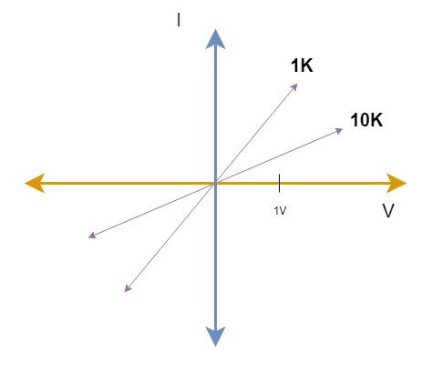
Voltage Current Characteristics of Resistor
To understand the working of resistor observe the above VI characteristics for a moment. VI – Voltage current characteristics graph usually shows the relationship between Voltage and current for a particular component. The VI characteristics for a resistor is pretty linear. As you can observe when current flowing through a resistor increases it results in raise of voltage developed across the resistor. Although different resistors with different resistance gives varied voltages when similar ampere of current flows through it. To simply we can say that Voltage across a resistor is proportional to the current flowing through it. Yes a resistor follows Ohm’s law since their relationship between current and voltage is linear in nature. Remember Ohm’s law states that “Current through a conductor is directly proportional to the voltage developed across it. This gives rise to the popular formula V = IR
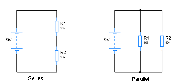
Using more than one resistor takes two forms: Series and Parallel. The above diagram shows connecting resistors in series and parallel configuration. Important thing to remember that is when resistors are in series resistance adds up. Meanwhile when resistors are in parallel overall equivalent resistance reduces.
The equivalent resistance of series resistors R1 and R2 will be Req = 10k + 10k = 20k
The equivalent resistance of parallel resistors R1 and R2 will be 1/ Req = ( 1 / 10k + 1 / 10k ) = 5K
A tip to solve parallel resistance quickly : When parallel resistors used in a circuit is of same value then divide the resistor value by the number of resistors connected in parallel. For example if 3 resistors of 10K is connected in parallel, 10k / 3 will give 3.33k which is the equivalent resistance.
APPLICATIONS OF A RESISTOR:
Now we have come to the most interesting part of this tutorial. By now you should have fair understanding of what is resistor and how does it work. Let’s take a look at it’s applications and how it is used in circuits. Resistor is used
As Voltage divider to feed reference voltage
Current limiters to prevent damage of components
To provide feedback
As Filters for input signals
Timing circuits to generate time delay
Pull up and Pull down resistors to fix the logic levels in digital circuits.
Load resistors
VOLTAGE DIVIDER:
Voltage divider is a pretty famous setup using resistors and widely used in circuits. The main job of voltage divider is to divide the input voltage into a fraction as output. This is particularly very useful to generate a reference voltage in our circuits. Reference voltages are often used in comparators, sensor circuits, Trigger circuits and so on. Let’s take a look at an example circuit where voltage divider set up is used to produce the reference voltage.
Resistors in Voltage divider
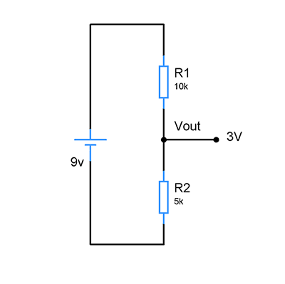
As you can see in the above circuit diagram. The input voltage from Vcc is about +9v to the voltage divider and the output voltage is 3v. What happens here is Resistor R1 drops 6v and R2 drops 3v totaling 9v. The output voltage of voltage divider is governed by the equation
Vout = Vin x R2 / (R1 + R2) .
Vout = 9V x 5K / ( 10K + 5K )
= 3V
As already stated voltage divider is widely used in electronic circuits to produce reference voltage, shifting levels of signals and so on. But always remember Voltage dividers should not be used as a voltage source to power circuits. If you attempt to do so the Voltage from the divider will drop significantly. This happens since Voltage divider cannot supply current to meet the needs of circuits so it drops voltage when more current is drawn from it.
Another few things to remember about voltage dividers is that when R1 and R2 is equal then output voltage will be half of the input voltage. If R1 is very much greater than R2 ( R1>>R2 ) then output voltage will be close to or almost equal to zero. When R1 is very smaller than R2 ( R1<<R2) resultant output voltage will be will be close to or almost equal to input voltage. These things will save you some time when analyzing circuits.
CURRENT LIMITING RESISTOR:
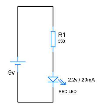
This is one more significant application of resistor. As the name implies it limits the flow of current through the circuit. The reason why we do this is because there are few instances where we need to allow only certain amount of current to flow through or the circuit/ component might end up being damaged. Current limiting resistors are commonly used for LED, Motor, Battery charging, relay etc.
Resistor to limit the current
Here in the above circuit, current limiting resistor for LED is shown. Let’s get into the calculation part of the above limiting resistor. The circuit is powered by 9v battery, however the LED we have here has forward voltage of 2.2v and consumes only 20mA to operate. So we need to limit the current from 9v battery to 20mA using the resistor.
R = V – Vled / Iled
= 9 – 2.2 / 20mA
6.8 / 20mA
= 340 ohms
and we choose the closest value of 330 Ohms as R1. This 330 ohm resistor limits the current to 20mA for LED and protects it from getting damaged from current. The above formula applies when you need to limit current to motor, relays, batteries and such.
RESISTOR AS FEEDBACK ELEMENTS:
Feedback is a concept used in Operational Amplifiers popularly known as Op Amps. In order to understand the need of resistor as feedback element we need to understand the working of Opamp. Am not going to go in depth of OpAmp here but going to scratch the surface a little bit. Simply put Opamp is an amplifying device which amplifies the difference between its two input terminals ( Non inverting and Inverting one ). This Opamp has Infinite gain which means it is capable of amplifying the input signal infinitely. Although its practically not possible but Opamp’s gain is so high that when you apply a input signal the output swings to its peak saturation voltage. We don’t want that in an amplifier because we need a boosted replica of our input signal and that’s why we use an amplifier.
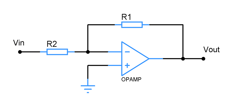
Negative Feedback
If we need to get an amplified signal from Opamp we need to control its gain. For that purpose a portion of output is fed back to the inverting input of Opamp making it a Negative feedback system. In the above circuit R1 is the feedback resistor. This feeds a portion of output back to the inverting input of Opamp. Negative feedback affects the gain of Opamp and keep the amplification under control. Thereby we will get an amplified signal that’s still usable for our purpose. So in a nutshell Feedback is a correcting mechanism in a circuit for the circuit to operate in a stable and equilibrium state.
For a positive feedback system portion of output is fed back to the non inverting input of Opamp. This type of feedback is used to increase the gain. Positive feedback is not widely used as much as Negative feedback configuration.
FILTERS:
Resistors are also used to filter incoming signals when used with Capacitors. Filters are used widely in many electronic circuits where it will allow signal of certain frequency and attenuates the undesired frequencies. There are two forms of Filters: Passive and Active ones. Resistor forms an integral part of Passive filters along with Capacitors and Inductors. There are three important types of Filters which can be constructed using passive components like Resistors, Capacitors and Inductors. Low pass Filter, High pass Filter and Band pass filter.
LOW PASS FILTER:
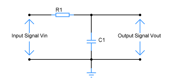
Design of Low pass filter
Above shown is a simple low pass filter designed using a Resistor and Capacitor. Low pass filter allows only the low frequency signals which is the signals with frequency less than cutoff frequency to pass through and blocks the high frequency components in the incoming signal. What happens here is that at low frequencies Capacitor exhibits high reactance compared to resistor R. The voltage across capacitor at this point is very high compared to voltage across resistor. Therefore it safely allows the low frequency signals to pass through. At high frequencies Capacitor reactance becomes low and therefore voltage drop at resistor becomes high and therefore attenuating the incoming signal.
HIGH PASS FILTER:
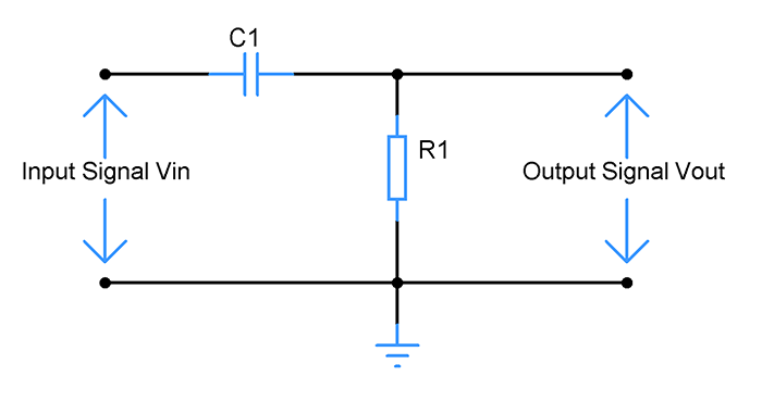
Design of High pass filter
Above shown circuit is a high pass filter which attenuates the low frequency signal below cutoff point and allow only the high frequency signals. What happens here is when incoming signal frequency is very low capacitor shows high reactance therefore acting as a open circuit leading to attenuation. When incoming frequency is higher than cutoff frequency capacitor exhibits low reactance therefore allowing the signal to pass through.
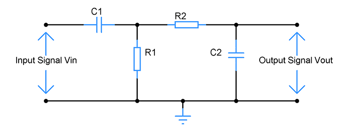
BANDPASS FILTER:
Design of Band pass filter
Band pass filter is a combination of both high and low Pass filter. Unlike above filters band pass filters have two cutoff frequencies. Hence this filter allows signal only within a particular band of frequencies. The signal with frequency outside this band will be attenuated.
In all the above the cutoff frequency is very important since it decides the frequency at which a signal will be allowed to pass through or attenuated. Filter design is quite a big concept to explain in this article will write a dedicated tutorial for it soon. For the scope of this article it’s important to understand the part of resistors in Filters.
TIMING CIRCUITS:
Using resistors in timing circuits is quite a common application. Timing elements are popularly know as RC circuits where a Resistor and capacitor works together to generate a certain amount of time delay based on the component values.
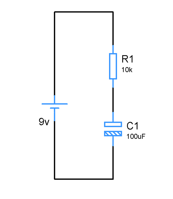
RC timing circuit
The above given is a RC circuit which just uses a Resistor and Capacitor to generate the required time delay. This timing is governed by the formula T = RC where T is referred as Time constant. So applying the above values in this given formula will yield 1 sec of time delay using this circuit. But it’s not all with this circuit, in order to understand the RC circuit fully you need to understand the the working of Capacitor, especially its charging curve. Am not gonna discuss about Capacitor working in detail but gonna scratch the surface to understand this timing circuit better and what’s the role of Resistor in it.
When Voltage applied across a capacitor current flows through it and Capacitor gradually starts charging. This induces voltage across its terminals to increase. The voltage across a capacitor increases gradually and not instantaneously and this generates a time delay. Once the capacitor reaches the supply voltage or Vcc it stops charging and allows no current. In this state the Capacitor is considered to be fully charged. The time taken from the zero charge state to full charge state produces the time delay and this is illustrated by Capacitor charging curve as show in the below diagram.
CHARGING CURVE:
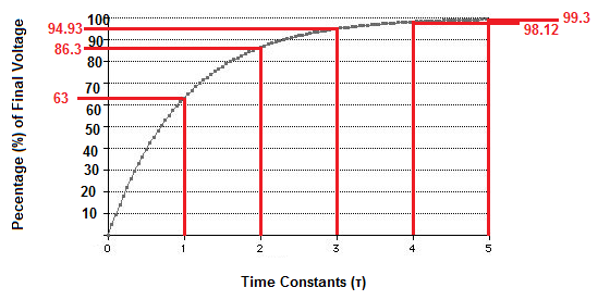
Capacitor charging curve
If you observe the above charging curve we can derive that it takes 5 Time constant or 5T to achieve 100% charge which is the supplied voltage. As we have seen earlier one time constant T = R x C which only gives a time period of 63% of total Capacitor charge. So in order to calculate the time taken for Capacitor to charge fully is given by the formula T = 5 x R x C or 5T. The main function of Resistor in an RC or Timing circuit is to control the flow of current to Capacitor. This will influence the time delay generated.
So coming to the circuit above it takes 1 sec or 1T to charge Capacitor up to 63% of Vcc ( 9V ). And it takes 5 secs or 5T for Capacitor to reach the supplied voltage of 9v. Thus this simple RC circuit is capable of generating a time delay of 5 seconds. This RC element is used along with other circuits in a way where voltage across Capacitor is monitored as input and desired time delay is achieved.
PULL UP AND PULL DOWN RESISTORS:
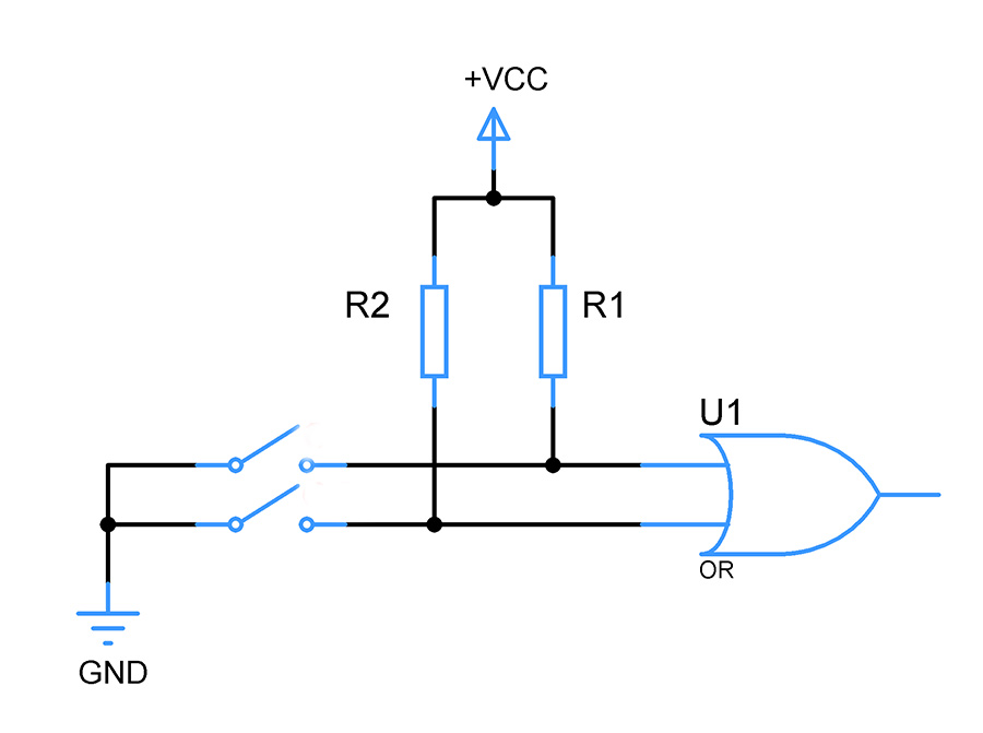
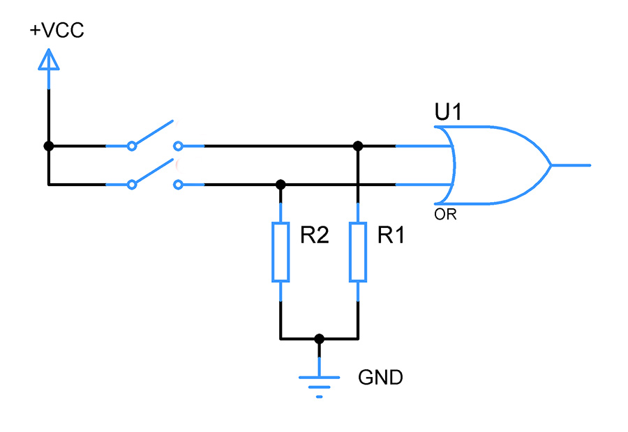
Usage of Pull Up resistors
Pull Up and Pull down resistors is something that you will find in most of the digital circuits. We all knew digital circuits operate in means of logic levels. Let’s consider TTL logic to explain this better. In 5v TTL logic devices in order to achieve logic 0 input voltage must be within 0 to 0.8v whereas for logic 1 Input voltage must be within 2 to 5v. So what happens is, digital input pins are very susceptible to Electromagnetic interference from external surroundings. This EM interference induces voltage on these input pins which will lead the IC to read incorrect voltage level.
To avoid this above situation we use resistors in two ways, Pull up and Pull down. Pull Up resistor pulls the voltage level of input pin to the level of Vcc. Pull down resistor pulls the voltage level of input pins down to 0v. Using this way we can be sure that our digital input pin stays at a predictable state.
In Electronics Load is referred to device or component which draws current from a circuit and connected to its output. So Load resistor is a resistor that is connected at the output stage of a circuit to draw current from the circuit. The term Load resistor is often comes into practice in mathematical modelling of a circuit. Here any device can be used with the circuit to draw current from its output. In such instances a resistor of particular value is chosen as a Load resistor to simulate the current draw equivalent to the device that is intended to use in the output. To simply put Load resistor is used to perform mathematical calculations and analyse the circuit for its ability to handle the current draw under a load.
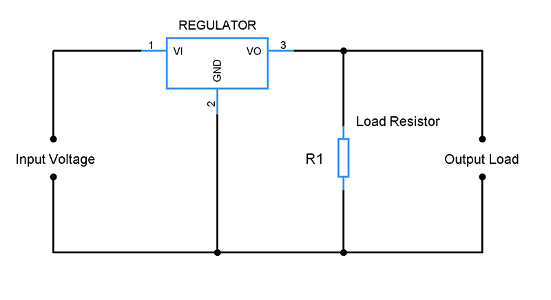
Usage of Resistor as Load
With that’s being said about Load resistors, there are cases where Load resistors will be a part of practical circuit rather than just being used only for mathematical modelling. There are voltage Regulators where it is necessary to use a load resistor. In the above circuit Resistor R1 is used as Load resistor. This draws minimal current to keep the functioning of regulator stable. And in Transistor amplifiers Load resistor will be commonly used to prevent excess current run off between Collector and Emitter and this in turn prevents the transistor from being damaged. So to sum up Load resistors are used for mathematical modelling. But there are cases where it is used in practical circuits.
WATTAGE RATING OF A RESISTOR:
This is one important criteria of a resistor that we should be aware. Resistors resist current flow for a given voltage, when this happens resistor heats up due to dissipated power. Wattage rating is nothing but the amount of power a resistor can safely dissipate. When the power dissipated exceeds the wattage rating of a resistor, its likely to be destroyed or smoked. Every resistor has it’s own Wattage rating. Through hole components usually rated as 0.25w and have rating higher than that.
Power dissipated in a resistor can be calculated using the formulas P = I2R or P = V2 / R. Consider you are driving a LED of 2.2v with 12v with a 330 ohm resistor in series. In this case the power dissipation in the resistor will be
VRes = 12 – 2.2 = 9.8v
P = 9.82 / 330 = 0.29 Watt
In this case you have to use a 0.5 Watt resistor to safely operate in the circuit.
FINAL WORDS:
Hope this tutorial will be very useful to you all. The above mentioned applications of Resistors has great significance and widely used. Do bookmark this page and come back later. If you have any questions related to this tutorial, please feel free to leave a comment below. I will be happy to answer them. Please share your feedback and thoughts about this tutorial below as well.
Am working on tutorials of important components used in Electronics and will be publishing them in upcoming days. Do subscribe to our Weekly Newsletter and Follow us via Social media channels to get updates on these tutorials. Happy learning 🙂
You make a mistake in wattage calculations.
Using 12V power supply you need 490ohm resistor and the power dissipation will be 0.196Watt so you need an ordinary 1/4 Watt resistor.
To Use 330ohm resistor power supply must be 9V and the power dissipation will be 0.132Watt


You make a mistake in wattage calculations.
Using 12V power supply you need 490ohm resistor and the power dissipation will be 0.196Watt so you need an ordinary 1/4 Watt resistor.
To Use 330ohm resistor power supply must be 9V and the power dissipation will be 0.132Watt
This is Geofrey from Uganda
It’s really awesome to come across this platform