Inductor is a passive component in Electronics and considered most important one after Resistors and Capacitors. Speaking of Inductors, it is nothing more than a wire wound tightly around a core. This tutorial is written to provide good understanding about Inductor working and how to use them in practical circuits. This tutorial focuses on three important questions that an enthusiasts will have about Inductors.
By the end of this tutorial you will have a good understanding about Working of Inductors. Also you will be able to recognize the use of Inductors in any circuits you will see. You can check out our tutorials about other components
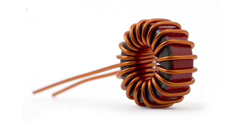
As already stated Inductor is nothing more than a insulated wire that is wound tightly around a core. This core can be of Ferromagnetic material or plastic or in some cases hollow ( air ). This relies on the principle “Magnetic flux develops around a current carrying conductor”. If you know about Capacitors you will be familiar with the fact that a Capacitor stores energy by storing equal and opposite charges in its plates. Likewise Inductor stores energy in the form of Magnetic field developing around it. Inductors react differently with AC and DC. But before digging deep into the “Working of Inductors”. Let’s see about its construction and characteristics.
CONSTRUCTION OF INDUCTOR:
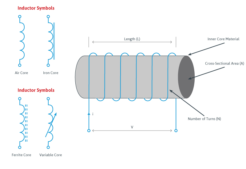
Inductor is pretty simple to construct out of all other components used in Electronics. Here is a guide to make a simple Inductor. All it takes is a insulated wire and a core material to wound the coil. Core is nothing but a material on which the wire is wounded as shown in the above diagram. There are different types of Inductors based on the core material used in it. Some of the common core materials used is Iron, Ferro magnets and so. Apart from the types of core material, it comes in different size and shapes from Cyclindrical, Rod, Torroid and Sheets. In contrast to this there are also Inductors which doesn’t have any physical cores. They are known as hollow core or Air core Inductors. The core plays an important role in altering the inductance of an Inductor.
HOW DOES AN INDUCTOR WORK
Let’s start with stating the fact “Magnetic flux will be developed across a current carrying conductor”. Likewise when current is applied through an Inductor, it develops magnetic flux around it. In other words energy applied to an Inductor is stored in the form of Magnetic flux. The direction of Magnetic flux developed will be in opposite to the direction of flow of current. Therefore Inductors resist sudden change in current flowing through it. This ability of Inductor is termed as Inductance and every Inductor will have some inductance in it. This is given by the symbol L and measured in Henry.
Inductance of an Inductor depends on the shape of coil, number of turns of winding over the core, area of the core and permeability factor of Core material. The inductance of an Inductor is given by
L = μN2A / l
L – Inductance of the coil
μ – Permeability of the core material
A – Area of coil in Square meters
N – Number of turns in coil
l – Average length of coil in meters
INDUCTORS IN AC CIRCUITS:
As stated earlier Inductor acts differently to AC comparing to DC signal source. When AC signal is applied to Inductor, it produces a magnetic field which is varying in time because the current producing the field is varying in time itself. This phenomenon according to Faraday’s law produces a self induced voltage across the Inductor. This self induced voltage is denoted by VL. In fact the voltage developed across the inductor act on the opposite direction to the current flow resisting them. This voltage across the Inductor is given by the formula
VL = L di / dt
VL – Self induced voltage
di / dt – Change in current with respect to time
If 1 Ampere of current with respect to one second when flows across one Henry Inductor will develop 1v across the Inductor. Now you see how current flowing through inductor affects the voltage developed across it. This voltage developed acts in opposite to the current flow through the Inductor.
V-I CHARACTERISTICS OF INDUCTOR:
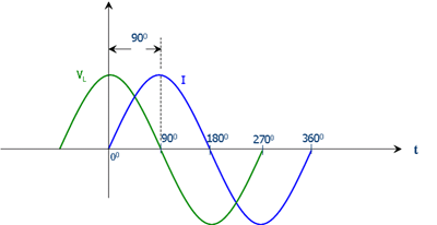
Let’s understand the above concepts better by referring to VI characteristics curve of an Inductor. When positive cycle of an AC signal passed through an Inductor, current flow increases. We know Inductor hates change in current so it develops a Induced voltage to act against the current flow that’s causing it. You can observe this in 0° in above graph that Induced voltage will be maximum when current started to raise. Once the current reaches the maximum, Induced voltage goes negative to try and keep the current flow from decreasing.
This cycle repeats itself and from the above graph we can observe that Induced voltage developed in an Inductor will act against the changing current flowing through it. And here Voltage and Current is said to be out of phase by 90°. Thus with an AC signal the Inductor stores and releases energy in the form of magnetic field in a continuous cycle.
INDUCTOR IN DC CIRCUITS:
We now have an idea of how Inductor works with AC signal source. Let’s take a look at how it reacts when used with DC signal source. Recall the induced voltage formula across the Inductor is given by
VL = L di / dt
When using a DC signal source the change in current with respect to time will be zero resulting the induced voltage across the Inductor to be zero. To put it simply in DC circuits Inductor behaves like a simple plain wire with some resistance caused by its wire. But there is more to it when using an Inductor with a DC signal source in practical circuits. In practical circuits there will be a brief period of time current takes to reach maximum value from zero. During this instant there will be an Induced voltage across the Inductor which will be Negative maximum when current starts moving from zero to its maximum value. Once current reaches stable DC condition, Induced voltage falls sharply back to zero and nullify. This short span of induced voltage will be exhibited as a voltage spike by the Inductor when using with DC signal source.
INDUCTIVE REACTANCE:
Another important thing to know about Inductors is Reactance. This is the resistive property exhibited by components like Capacitor and Inductor to Alternating current signal. The Reactance exhibited by Inductor is called as Inductive Reactance and given by the formula
XL = 2πFL
From the equation you can deduce the Reactance increases with the frequency of AC signal, remember Inductor hates changing current so it exhibits more reactance to high frequency signals. Whereas when the frequency is close to zero or DC signal is pass through Reactance becomes zero acting like a conductor for input signal to pass through.
APPLICATIONS OF INDUCTOR
Now we have came past the slightly boring and vague Inductor working section. Let’s learn how to use Inductors in Circuits. To do this let’s take a look at its applications. Applications of an Inductor is the most exciting part of this tutorial. This section discuss the most important applications / Circuits where Inductor is used. If you find Inductor in a Circuit anywhere , there is a high chance that it falls under one of the below uses of Inductors.
OSCILLATORS / TUNED CIRCUITS:
These are circuits that is used in Radio transmitters, Receivers, Oscillators and applications where frequency selection is important. Here Inductor works along with Capacitor to operate. If you know about working of a Capacitor you know that it exhibits high reactance to low frequency signals whereas Inductor offers high reactance to high frequency signals. In this circuit the Inductor and Capacitor value should be selected in such a way it provides equal reactance at a given incoming frequency. This state is said to be Reasonance and the related frequency is referred to as Reasonant frequency. At Reasonance this circuit is capable of generating signals of associated frequency to act as an Oscillator or receive signals of this frequency from a complex signal.
When the Capacitor in this circuit is charged, it stores charges between its plates. Once the supply is cut off, the current from Capacitor passes through Inductor resulting in developing a magnetic field around it. By this time charge stored in Capacitor would have depleted and current stops flowing to the Inductor. As we know Inductor loves steady current and as a result it will try to keep the current flow steady by collapsing its magnetic filed and enable the current flow back to Capacitor. The Capacitor will be fully charged again. The charge flows back and forth between Capacitor and Inductor resulting in generating signal of fixed reasonant frequency.
The Reasonant frequency is given by the formula f0 = 1 / 2π√(LC)
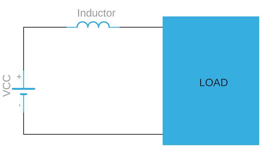
INRUSH CURRENT LIMITER:
Inrush currents also known as Surge current or Input surge current is pretty much capable of destroying circuits. These are instantaneous currents drawn by a load or electrical device as soon as it is turned ON. Astonishingly this inrush current can be 40 to 50 times higher than steady state current and potentially capable of destroying devices. Inrush current usually occurs due to instantaneous high current required by high value capacitors, Transformers to operate and must be prevented from reaching the equipment.
Inductor is widely accepted way to prevent the inrush current from damaging the circuit. When the circuit is turned ON the instantaneous high current which is changing with respect to time flows. Inductor opposes this change in current by developing a magnetic field around it which builds up a self induced voltage which opposes this high current from the supply. After for a moment when the current returns to steady state the magnetic field collapses and release the stored energy into the circuit in the form of current. Once the current becomes steady DC the Inductor will no longer oppose it and offers free path to the current flow through it.
FILTERS:
These are special type of circuits used to filter or eliminate signals of undesired frequency and only allows signals to pass through within the desired limit. Using Inductor along with passive components like Resistor and Capacitor we can build three different types of filters that can serve our signal filtering purpose.
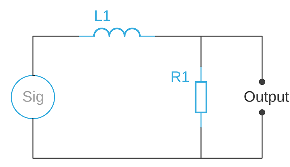
LOW PASS FILTER:
As the name implies this filter is used in circuits where you need to filter out signals of frequency higher than the cutoff frequency from the incoming signal. The term cut off frequency refers to frequency limit set by the value of components used in this filter. So here value of Inductor and Resistor decides the cut off frequency. This filter allows signal that has frequency below this Cutoff limit and above this limit will be blocked by this filter.
What happens in this filter is when the incoming signal is of high frequency, the reactance exhibited by Inductor will be very high. Reactance is decided by the Inductance value and frequency as we have seen in the formula XL = 2πFL. The inductor along with resistor forms a voltage divider where with higher frequency higher the inductor reactance ( resistance ) will be. Higher reactance enable Inductor to attenuate signals effectively and therefore at the output will be zero voltage or close to zero.
The cut off frequency this Low pass filter can be calculated using fc = R / 2πL
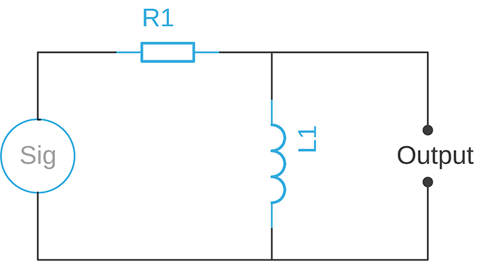
HIGH PASS FILTER:
Here in this High pass filter the places of Inductor and Resistor has been swapped. This filter only allows high frequency signals to pass through in contrast to low pass filter. Here signals with frequency higher than cut off frequency will be allowed. And signals with frequency below that will be attenuated / blocked. When signal of low frequency is passed through the circuit the reactance exhibited by Inductor will be very low comparing to resistance of Resistor, therefore voltage drop across resistor will be very high and output signal will be zero or close to zero.
When high frequency signal is passed through the circuit, Inductor exhibits high reactance compared to resistor R1. Therefore resistor offers very less attenuation to incoming signals making high frequency signals to reach output with very less or zero attenuation. By this way High frequency signal is allowed to pass through while low frequency signal is blocked.
The cut off frequency of this filter can be calculated using fc = R / 2πL
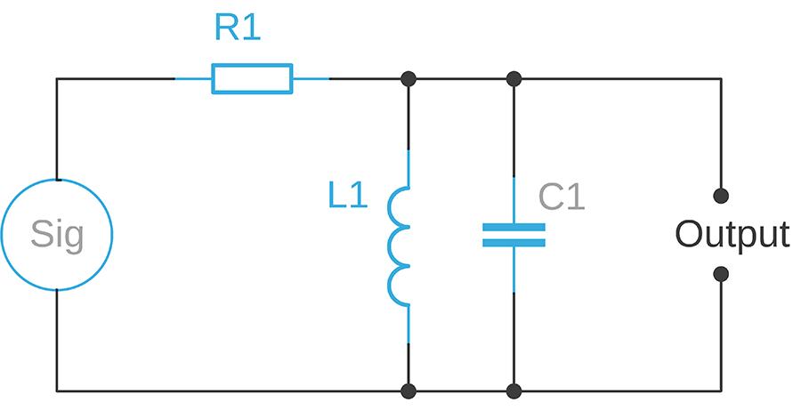
BAND PASS FILTER:
In this filter only a band of frequencies is allowed to pass through them and anything outside this frequency will be rejected. Unlike Low pass and High pass filter, band pass has two cut off frequencies. Upper and Lower cut off frequency and signal of frequency between these frequencies will only be allowed to pass through.
The working of this filter mainly depends on the Inductor and Capacitor connected in parallel. It is a tank circuit, as we have seen earlier in the tuned circuit. If you remember what you have seen from the Tuned circuit section, Reasonant frequency is the frequency where reactance of both Inductor and Capacitor to incoming signal will be equal. The reactance given by Inductor and Capacitor pair will be high comparing to Resistance of Resistor when incoming signal is close to or around the reasonant frequency. Therefore the band of frequencies close to the reasonant frequency will pass through the filter. The frequencies outside this band will be blocked.
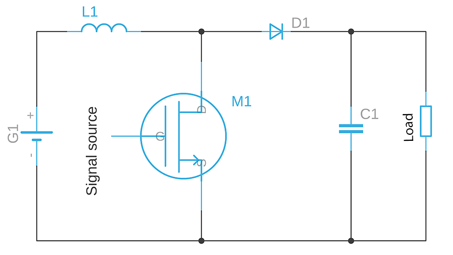
VOLTAGE BOOSTER:
Voltage Boosters are circuits that is used to boost the incoming voltage to a certain level. It exhibits higher voltage in the output than the input voltage. Inductors are most important thing in voltage booster circuits due to their property of developing self induced emf when current of alternating nature flows through it. The above shown is a typical Booster circuit where a DC supply is supplied to the Inductor. On the other hand a MOSFET is connected to it. The MOSFET will be turned ON and OFF at steady intervals by a signal source.
When MOSFET is turned ON the current flows from power supply to Inductor and then flows through the MOSFET. This develops magnetic flux as well as Self induced voltage across the Inductor. When MOSFET is turned OFF by means of signal source it leads to reduced current flow. Inductor will now attempt to keep this current flow steady. As a result Self induced voltage switches the polarity forcing it to act like a voltage connected in series with power supply G1.
This combined voltage ( Voltage from power supply G1 and Self induced voltage across L1 ) will force current through diode and charges the Capacitor to this voltage level. When the MOSFET is switched ON and OFF fast enough Capacitor will retain this voltage and exhibit this voltage level in the output. Thus using these kind of circuits you will get a boosted voltage at the output.
QUICK SUMMARY ABOUT INDUCTORS:
Inductor is a passive element which means it cannot generate energy on their own.
It opposes the changes in current flowing through it.
Inductor offers low resistance path when DC signal is applied to it.
When AC signal is applied Magnetic field forms around the Inductor resulting in developing a self induced voltage which opposes the change of current flowing through it.
In contrast to Capacitor, Inductor offers high reactance to high frequency signals and low reactance to low frequency signals.
Important applications of Inductors are in RF transmitters, receivers, Power supplies, Signal filters and so on.
That’s pretty much about Inductors and its applications in practical circuits. We suggest you to read this Inductor working and Applications tutorial twice to establish a strong understanding about Inductors. This tutorial must have helped you to identify the purpose of using Inductor in any circuits in the future. There are also other applications of Inductor which we haven’t covered in this tutorial which we will cover in another tutorial which will be published in upcoming days.
You can find tutorials about other Electronic components in our website here. We will be publishing more Electronic tutorials in the future. Do Subscribe to our Newsletter and follow us via Social media channels to get regular updates from our website. If you have any doubts that need clarification or further explanation do leave your questions in the comment box below. Or if you believe we have missed something important in this tutorial do let us know, we will add them.
Thanks very much for this particular tutorial about inductors please do include animations or videos on the working and how to use the inductors in circuits as this can as well improve on the perception easily since a learner can see what is happening right away.cheers okiror daniel a biomedical engineering technician from uganda.
Hello.
I just recently discovered your web site. Thank you very much! I am a beginner electronics hobbyist and I find many nice tutorials. Lessons accessible and easy to understand. I look forward to finding some free time to read and explore.
I wish you success and more and more users
Best regards: MladKal from Bulgaria your friends, followers, with pleasure
P.S: I will show and popularize your website among everyone
Raman,
In a nutshell Inductor stores energy in the form of magnetic field that is when voltage is applied across it, it turns in to a small magnet. However when voltage applied across capacitor it stores energy in the form of electric field that is it turns into a small battery.
Under the “OSCILLATORS / TUNED CIRCUITS” section you have “…Capacitor you know that it exhibits high reactance to low frequency signals whereas Inductor offers high reactance to low frequency signals…”. Did you mean “…Capacitor you know that it exhibits high reactance to low frequency signals whereas Inductor offers high reactance to *high* frequency signals..”


Thanks very much for this particular tutorial about inductors please do include animations or videos on the working and how to use the inductors in circuits as this can as well improve on the perception easily since a learner can see what is happening right away.cheers okiror daniel a biomedical engineering technician from uganda.
Hello.
I just recently discovered your web site. Thank you very much! I am a beginner electronics hobbyist and I find many nice tutorials. Lessons accessible and easy to understand. I look forward to finding some free time to read and explore.
I wish you success and more and more users
Best regards: MladKal from Bulgaria your friends, followers, with pleasure
P.S: I will show and popularize your website among everyone
Very good tuts.
What about Transistors. No Tutorials about that component. Need on to learn about Transistors.
Can you tell me the difference between Inductor and Capacitor. I am having hard time in understanding the difference between these two.
Raman,
In a nutshell Inductor stores energy in the form of magnetic field that is when voltage is applied across it, it turns in to a small magnet. However when voltage applied across capacitor it stores energy in the form of electric field that is it turns into a small battery.
Hope this helps
Great tutorial.
Under the “OSCILLATORS / TUNED CIRCUITS” section you have “…Capacitor you know that it exhibits high reactance to low frequency signals whereas Inductor offers high reactance to low frequency signals…”. Did you mean “…Capacitor you know that it exhibits high reactance to low frequency signals whereas Inductor offers high reactance to *high* frequency signals..”
Hey Wes,
Geez that was a silly mistake and thank you very much for pointing this out. I have made the corrections now. Cheers 🙂
Very helpfull tutoriel.Thank you so much.
Welcome. Do check out our other Electronic tutorials in our website – https://www.gadgetronicx.com/category/electronics/tutorials/
Thank you. Check out other Electronic tutorials here.