Kitchen timers are little gadgets that we use in our Kitchen to help us with cooking time of our food. Most of the Kitchen timers we use are mechanical ones and are susceptible to wear and tear. The above Digital Kitchen timer circuit however have pretty good accuracy than the mechanical ones and it only cost $3 to build one on your own. This circuit has the ability to choose between 20 and 30 min of cooking and can be expanded with addition of resistors and switch based on your timing requirement. Once the set time is elapsed a buzzer starts buzzing indicating the end of your cooking time.
COMPONENTS REQUIRED:
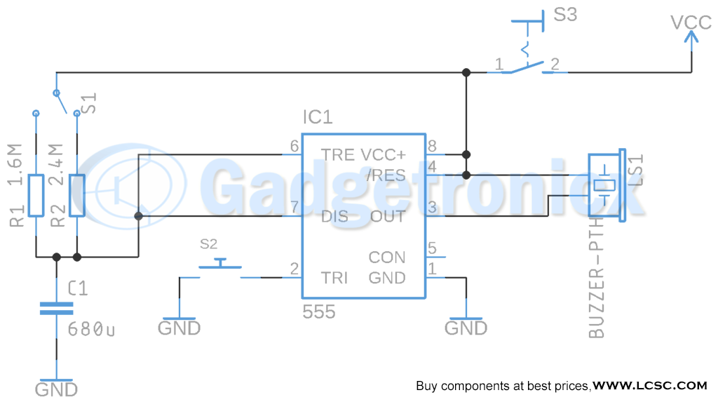
Battery between 9v
Capacitor 680uF
Resistor 1.6M, 39k
Timer 555
Switch SPST
Switch SPDT
Push Button SPST
WORKING OF KITCHEN TIMER CIRCUIT:
In this timer circuit we use 555 timer in Monostable mode and this forms the heart of our circuit. 555 Monostable Multivibrator as we know needs to be triggered by a low pulse input signal to pin 2 of IC 555. Once triggered 555 IC will give a high output via its Output pin 3. Important thing to note here is the Resistor R1 or R2 and Capacitor C1. This decides the timing of high signal in the output of IC 555. To understand this better you need to know about the working of IC 555.
Our aim here is to modify the timing of this output signal for 20 and 30 mins. This can be done by selecting the Resistor and Capacitor of appropriate value to generate this time delay for our Kitchen alarm. This timing is governed by the formula
t = 1.1 x R x C
TIMING CALCULATION:
For generating a delay of 20 or 30 mins lets fix the Capacitor value to 680uF. The time t in the above equation is given in measure of seconds. So for generating 20 mins of delay we need 1200 seconds of delay in this circuit. Let’s calculate the Resistor value that need to be used for generating 1200 seconds or 20 minutes delay.
Similarly for 30 mins of delay equals 1800 seconds of delay and calculating the Resistor value for that, we will get
R = 1800 / 1.1 x 680 x 10-6
R = 2.4 MOhm.
We can deduce from the above for 20 min timer we need to use 1.6Mohm and 30 min we need to use 2.4 Mohm. Here in the circuit we have used a SPDT switch to select between these Resistors to use with Capacitor C1. By selecting 1.6Mohm we are selecting the 20 min option and with 2.4 Mohm we are selecting 30 min option for our Kitchen timer. You can also add resistors for other timing ranges.
RESISTOR VALUES OF OTHER TIMING RANGES:
15 mins = 1.2 MOhms
10 mins = 820 KOhms
5 mins = 390 KOhms
So once you select the timing using S1 and apply the low pulse S2. The IC 555 will start the timing countdown and gives high pulse output in the pin 3. In this instance the Buzzer will not sound. This is because if you look at the circuit output from IC 555 was connected to the Negative terminal of the buzzer and Positive terminal is connected to VCC. So what happens here is that when user presses the trigger button S2 which is where the timer starts and during this time output from pin 3 will be high state and will keep the buzzer in Off state. But once the 20 or 30 mins is elapsed the output in pin 3 will go to low state and thus enables the buzzer to sound. The buzzer will continue to sound until you turn off the Kitchen timer using S3.
HOW TO USE:
Turn ON the timer using Switch S3 ( the buzzer will start sounding as soon as you turned it on since output of IC 555 will be in low state )
Now select time option 30 or 20 mins using the Switch S1.
Start the timer using the Push button Switch S2.
Cook your food or meal or do the required activity
As soon as the selected time elapsed, Buzzer will start sounding again.
If you need to use it further again Re-trigger it using Switch S2
Or Turn it off using Switch S3.
NOTE:
Changing the switch used and adding more resistors as per the calculation will give more timing ranges for your Kitchen timer
Use Push button as S2 to trigger the timer.
Use toggle switch as S3 to turn ON and OFF the timer easily.
It’s advised to add a Pull up resistor to button S2 to avoid floating state and proper functioning of the circuit.