NiMH batteries are used everywhere. These batteries are safe, versatile and easy to charge. In this article we will look into a DIY NiMH battery charger circuit- its working and calculations to choose the right components. This is a basic electronic circuit and its quite easy to build. This circuit which uses Opamp, transformer, Voltage regulator chip LM338, Transistors, some Resistors and Capacitors.
NiMH Batteries:
Each NiMH batteries is built using individual NiMH cells which connects in series or parallel to deliver higher voltage or higher current in its output. One NiMH cell has a nominal voltage of about 1.2V. When a NiMH cell is fully charged it will exhibit 1.6V across its terminals. Typically a 9V NiMH battery will have 8 cells connecting in series with each other. This will give a resulting output voltage of 1.2 x 8 = 9.6V. In order to effectively charge a NiMH battery, the charging voltage should be equivalent to its fully charged voltage which is 1.6V x 8 = 12.8V.
Also charging current of the battery need to be considered along with the charging voltage. It is safe to charge a NiMH battery with half of it’s current capacity 0.5C. The battery which we going to use in this circuit is 9V/ 300mAH current capacity. Hence we need to charge the battery with 12.6v and 150mA which is equal to 0.5C.
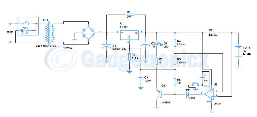
This NiMH battery charger circuit draws power from a wall socket power supply of 220v AC. À step down transformer is used to bring the voltage level to 18v. Four diodes are arranged in bridge rectifier configuration to convert AC signal to DC signal. Alternatively you can use a on chip bridge rectifier. The DC output voltage is the fed to Capacitor C1 which smoothes out the DC signal. The smoothed DC signal goes to LM338 IC.
LM338 is a voltage regulator chip in which the output voltage can be programmed using resistor R2, R4 and R5 in the above circuit. The formula governing the output voltage is
Vout = 1.25 ( 1 + R2 / ( R4 + R5 ) ) + IAdjR2
Using this formula the output voltage is set to 12.8V which is the charging voltage for 9V NiMH batteries. LM338 is capable of delivering up to 5A to the load. It is essential to use heat sink with LM338 voltage regulator.
The output voltage is then fed to the battery through a current limiting resistor of 80 Ohms. This resistor limits the output current to 150mA to charge the battery safely. Choose a high wattage resistor such as 10 Watts here, since it needs to withstand high current.
Charge indicator unit:
An Opamp was used as a charging indicator to show user that battery is fully charged. Here Opamp is built to operate as a comparator. A voltage divider was setup using R4, R5 and R6 to feed reference voltage to Opamp LM301. Combined resistance of R5 and R6 resistors is high in comparison to R4 so voltage reference set to positive input of Opamp measures around 12.7v which is almost equivalent to the fully charged battery voltage.
Let’s say uncharged battery is connected to the circuit. When battery is undercharged reference voltage to negative terminal of Opamp will be less than 12.7v. Whereas voltage reference from voltage divider network to its positive terminal will be equal to 12.7v. This forces output of Opamp to high state. This keeps the PNP transistor in OFF state and current flows to battery and charges it.
When battery starts charging, voltage across battery starts raising. When battery is fully charged, voltage in inverting terminal of Opamp will be greater than non inverting terminal. Thus Opamp switches its output to low state. This turns the PNP transistor ON.
Now the incoming current from LM338 will be sinked into Opamp output since battery voltage is nearly equivalent to LM338 output and Opamp output pin provides a path to current flow. Since PNP transistor is switched ON it will light up the LED, this will serve as an indicator to user to disconnect the battery from the circuit since battery has completed its charging cycle. Now user needs to disconnect the battery from the charger circuit.
> These batteries are safe, versatile and easy to charge.
No they are not! This is not an NiMH charger. NiMH are the hardest of all batteries to charge. You need delta volt, delta temp and current monitoring. They are also very dependent of correct charge current. To high or low, and you don’t see the delta volt. The delta temp is there as a security.
PLEASE DON’T BUILD THIS!
> nice information and well written .
It might we well written, but it is terrible information.
Hi,
What’s the purpose of the push-button?
“Opamp measures around 12.7v which is almost equivalent to the fully charged battery voltage. ”
That’s way too high for 6 or 7 cell pack.
nice information and well written .