Pull up and pull down resistors are integral part of many digital circuits. It is important to understand what is pull up or pull down resistors? Why it is used in digital circuits? and how to choose the value of these? This article will answer these three questions and give you a better idea about it.
VIDEO EXPLANATION:
WHAT IS PULL UP OR PULL DOWN RESISTORS:
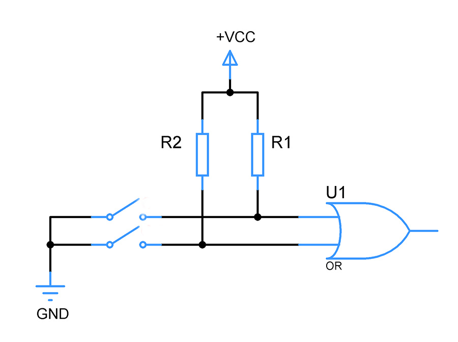
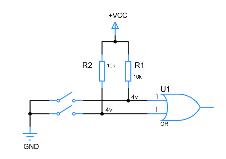
These are common resistors that connects the digital input pins to VCC or Ground. The purpose of these resistors is to bring up the input pins equivalent to the voltage of Ground or VCC. Refer the above circuit diagram the resistors R1 and R2 is the Pull up resistors. These resistors are pulling up the voltage of input pins to the level of VCC.
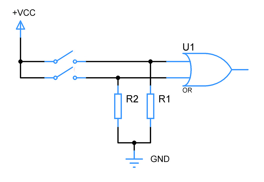
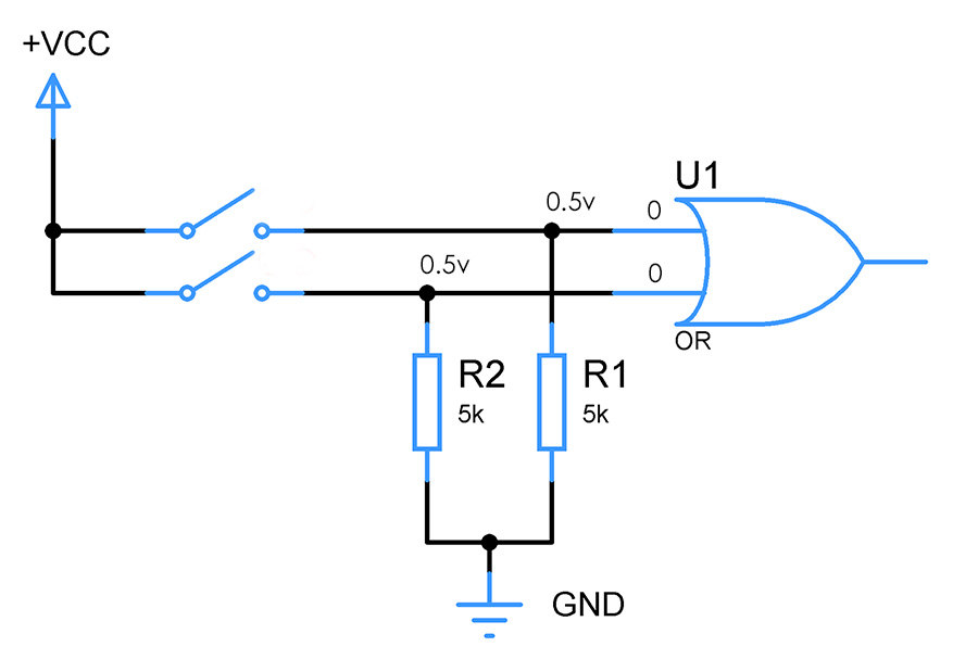
Now take a look at the above circuit diagram, here the resistors R1 and R2 act as pull down resistors. These resistors are pulling down the voltage of inputs pins close to the level of GND.
WHY USE PULL UP OR PULL DOWN RESISTORS:
In short the purpose of Pull up or Pull down resistor to give keep the input of digital pins at a stable state – 1 in case of Pull up resistor and 0 in case of Pull down resistor. To explain this further, we need to understand about Logic families and how each family differs from each other.
LOGIC LEVEL:
Logic level is nothing but the voltage range which decides how an input or output in a digital circuit is interpreted either as a “1” – high state or “0” – low state. There are many logic family exists in digital systems. TTl, CMOS, RTL, DTL are few of the families and out of which TTL and CMOS are quite famous and commonly used.
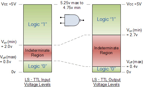
The above image shows the logic level diagram of TTL logic family of +5Vcc. As you can observe in both output and input diagrams, there is a voltage range for each logic states. Referring to input voltage levels, you can observe
For the Gate to read Logic 1 – Input voltage range must be between 2v to 5v
For the Gate to read Logic 0 – Input voltage range must be between 0 to 0.8v
The indeterminate region is the pitfall, this means when input voltage falls between from 0.8 to 2v the Gate will not understand it and it will act in an undesirable manner. Output could be either 0 or 1 and we can’t predict them.
The last case is too bad for designing a digital circuit, since it may make the entire circuit to fail and your design will do no good.
FLOATING STATE:
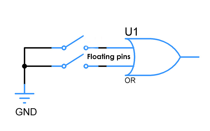
Now take a look at the above circuit where a switch is connected to the input pins of OR gate. When the switch is not connected the pins are said to be in a floating state which means no defined voltage is exhibited in it. In this instant Electrical noise or EM waves from the surrounding will induce some voltage in these pins and as a result there are high chances that the input voltage falls into that indeterminate region of 0.8 to 2v and thereby pushing our entire system to fail. In worst cases the noises and EM waves will produce fluctuating voltage making the entire system unstable.
To get rid of this above scenario add a resistor to both the input pins and connect them to Vcc. By doing this the input pins voltage will be pulled up and the voltage will be nearly equivalent to Vcc. This makes the logic gate to detect the input voltage as Logic 1 and act accordingly.
CALCULATING THE RESISTOR VALUE:
Every digital input pin consume some current and has some internal impedance in it. Due to these reasons voltage drop exists across these Pull up resistors. So when choosing the resistor value we should make sure
That the resistor is not too high so that it won’t allow enough current for input pin to operate
Too small so that excess current flows through and lead to short circuit.
PULL UP RESISTORS:
Let’s assume that our digital pin of OR gate consumes 100uA at +5Vcc. I have choosen 4v as Pull up voltage for the purpose of choosing resistor since it will give some nice room from 2v beyond which lies the indeterminate region. You cannot choose 5v since there will be some voltage drop in across the resistor as stated above, so it’s safe to choose less than the level of Vcc. Applying ohms law with these values,
R = 5 – 4 / 100uA
= 1 / 100uA
= 10Kohms
PULL DOWN RESISTORS:
With the above current of 100uA of consumption, am going to choose the pull down voltage of 0.5v since it gives a room from the 0.8v above which the input enters the indeterminate region. Applying ohms law here will give resistor value of
R = 0.5v / 100uA
= 5Kohms
NOTE:
Check the datasheet for input current and input impedence of your digital chip and perform the above calculation to find the perfect pull up or pull down resistor for your digital circuit.
Never attempt to try the above setup without resistors, you will end up shorting your power supply since closing switch without resistors will lead to excess current flow since no impedance is available.
Hope this tutorial would have been a great help for you. Do post your comments, queries and feedback about this below, Happy DIY 🙂