
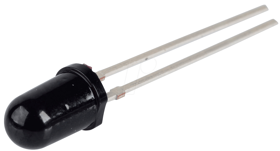
Photodiodes are one of the popular components used to sense incident light in electronic circuits. It has wide range of applications like Remote control, alarms, sensory applications and so on. This article explains What is a Photodiode, How it works and how to use them in a circuit.
Working of Photodiode :
To understand Photodiode we need know what is diode first. Am not gonna go into detail but diode is a component which only allows current in one direction ( only in forward bias ). When reverse biased diode will block the current.
Coming to Photodiodes it exhibits the same property allowing current when forward biased. However when reverse biased it resists the current until light is incident on it. When light falls on Photodiode current starts flowing through it which depends on the intensity of incident light on Photodiode. When current flows through the Photodiode voltage will develop across it and we will make use of it in our circuit to detect the incident light.
VI Characterstics:
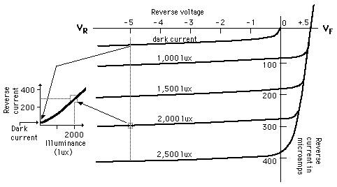
Let’s understand this better by taking a look at its VI characteristics. In the below curve you can notice the current flow through the diode for different light conditions. When the intensity of light less the current flow through Photodiode is less however when intensity of incident light increases we can notice the increase in current flow through the diode. Also another interesting fact to notice is that the voltage applied to Photodiode has little effect on the current flow and it largely depends on the incident light on the diode.
Using Photodiode in your circuit:
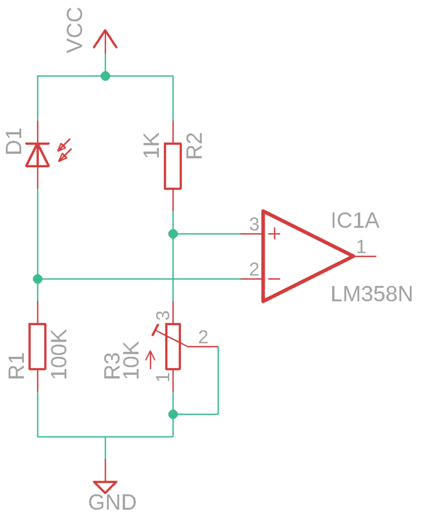
So we now know what is a Photodiode and how it works. Let’s see how to make Photodiodes work for you by using them appropriately in your circuit. So we know Photodiodes only detects light and react when reverse biased. So we are gonna position it in reverse bias state ( Cathode kept at higher potential comparative to Anode ). In this case current flows when light falls on it but we are more interested in the voltage developing across Photodiode since the current flow will be too low. So we have to use another resistor in series with the Photodiode forming a Voltage diver setup.
In the above circuit you can notice that voltage divider setup using Photodiode and resistor R1. The voltage developed between these two components is fed to inverting input of Opamp. Meanwhile another voltage divider using resistor R2 and R3 is used to create a reference voltage, adjust R3 to fix the reference voltage. When there is no light incident in the Photodiode no current flows and as a result voltage input to inverting input will be close to zero. So voltage at non inverting input will be high and output of opamp will be in high state. However when light falls on Photodiode current flows and as a result voltage will be developed across R1. Now voltage at inverting input will be high and therefore output of opamp goes low.
Of course this is not the only way to use a Photodiode but this is the most commonly used circuit when comes to Photodiode.
Note:
- Voltage drop across diode increases with intensity of incident light (since the current flow will increase with intensity of light).
- Use large value resistors in series with Photodiode to obtain high voltage range which will prove useful for feeding it to comparator input.
Things to remember:
- Photodiode works like a normal diode in forward biased state and responds to incident light in reverse biased state only.
- Intensity of incident light influences the current flow through the diode
- Current flow through it will be very less usually in range of microamps ( uA ).
- Reverse bias voltage has very less or negligible impact on current flow through Photodiode.


")
