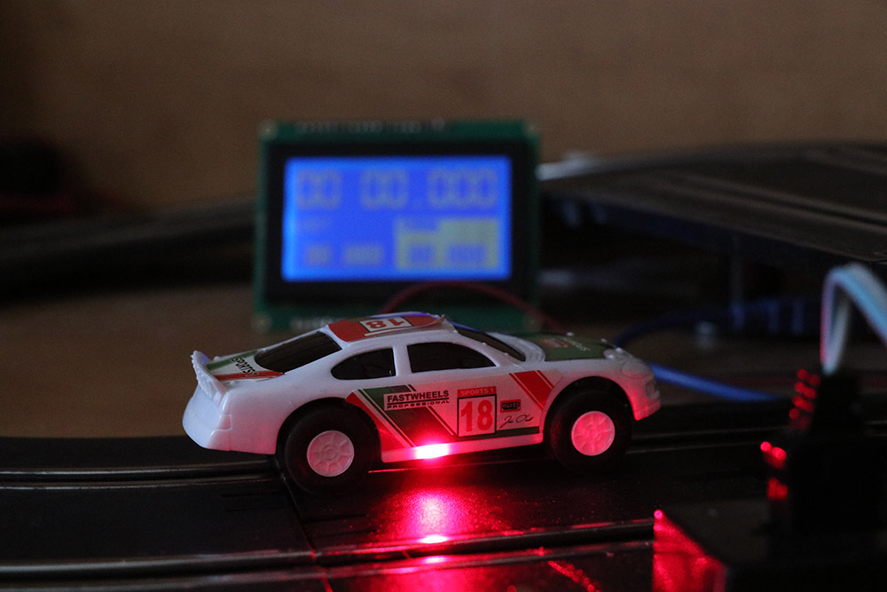
I ordered a pair of a KY008 laser module and 2 matching sensors. When I ordered them I had no idea what I’m going to do with them. But when they arrived I had a slot car 8 figure race track on the table, from a different project I was working on and it all came together. So I thought to build a project that will count the timings and number of laps made by the slot cars. This is a super fun project and certainly will spice up your Slot car racing especially if you have kids around they will love this project.
Warning: this laser module even that are very low power can and will damage your eye if you look directly into it! I located the laser in a way that it will point a way from people and will be VERY hard to put your eye in front of it!
PARTS REQUIRED:
KY008 Laser module
IS0103 Receivers
Arduino Mega
GLCD Module
Connecting wires
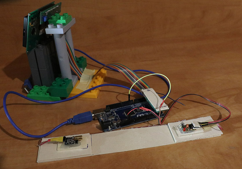
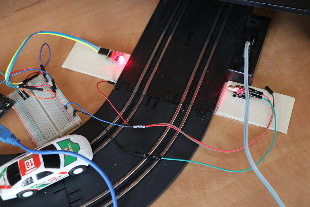
CONSTRUCTION OF LAP TIMER USING LASER AND ARDUINO:
The build is really simple and uses the laser and sensor as a switch. The KY008 has 3 pins, in most of the ones I saw only 2 were marked. The S pin and – in most of them the middle one is the +. So what I did (since I wanted it be ON all the time) is to connect the + and the S to the 5V and the – to the ground. If you want to control the on/off state of the laser as well, you can connect the S to any digital pin and declare it as output. Using it to switch the Laser ON or OFF.
The sensing module is based on IS0103 receiver that is sensitive to very bright light. So it’s perfect for the laser, I was able to trigger it with a very bright flashlight. The sensor module breakout I bought had 3 well marked pins. VCC, GND and OUT. Connect VCC to 5V, GND to GND and the OUT to the desired input pin on the Arduino. In my project I have used pin D2.
For the display I used a GLCD. The main reason is its size, and I had good amount of room on the table. I found it hard this time to find the info I was looking for its connection so here is the link for the pinout. Please note that there are 4 (A-D) type of pinout configurations. Refer this link to know more about the GLCD used in the project. Unfortunately connection diagram for this project is too messy to add it here. You can refer the links included and the Project video to get more clarity on how to connect the parts for this project.
I used this well documented library OpenGLCD, that also had a perfect example of running time which I have tailored it for my project purpose. The hardest part of the build was to align the two so each time the car crosses the path, sensor will get triggered since it will break the Laser line. But once I got it in place it worked perfectly.
CODE:
The code is very simple and well commented. It is a combination between the debounce switch example, which is what controls the laser trigger, and the other part is an example of running timer (from the GLCD library) that I altered a bit for what I needed.
#include "openGLCD.h"

// laps info
unsigned long currentRunStartMillis;
unsigned long lastRunInMillis;
unsigned long bestRunInMillis;
int currentLap;
unsigned long savedMillis;

gText t1; // will define runtime later
gText t2; // will define runtime later
gText t3; // will define runtime later

// global for display
int sec_val, milli_val;

// laser gate
const int gateSensorPin = 2;    // the number of the gate sensor pin
int gateSensorState;             // the current reading from the sensor
int lastgateSensorState = LOW;   // the previous reading from sensor
unsigned long lastDebounceTime = 0;  // the last time the sensor pin was toggled
int debounceDelay = 50;    // the debounce time; increase if the output flickers
Define the pin mode, define the needed GLCD area and area settings. Reset all the variable.
void setup() {
  // pin mode
  pinMode(gateSensorPin, INPUT);
  delay(50); // to late the sensor and laser work, so we wont get the lap triggered.
  // start GLCD
  GLCD.Init(NON_INVERTED);
  // define areas
  t1.DefineArea(textAreaTOP, lcdnums14x24);
  t2.DefineArea(0, GLCD.CenterY, 8, 2, fixednums7x15);
  t3.DefineArea(GLCD.CenterX, GLCD.CenterY, 8, 2, fixednums7x15);
  t3.SetFontColor(WHITE); // set font color
  t3.ClearArea();
  // print text
  GLCD.SelectFont(System5x7);
  GLCD.CursorTo(1, 4);
  GLCD.print("LAST");
  GLCD.CursorTo(11, 4);
  GLCD.print("BEST");
  // reset params
  currentRunStartMillis = 0;
  lastRunInMillis = 0;
  bestRunInMillis = 0;
  currentLap = 0;
}
The first part of the loop takes care of the laser trigger section. Note that I only do an “action” when the trigger gets to LOW, which means Laser was broke. Also note the difference between currentLap > 0 and not. When its not >0 it means it’s the first run and we only start the count. This is also the part where we check for best lap.
void loop()
{
  // read the state of the laser sensor:
  int reading = digitalRead(gateSensorPin);
  // If the switch changed, due to noise or pressing:
  if (reading != lastgateSensorState) {
    // reset the debouncing timer
    lastDebounceTime = millis();
  } //end if

  // if passes the debounce time
  if ((millis() - lastDebounceTime) > debounceDelay) {
    if (reading != gateSensorState) {
      gateSensorState = reading;

      // If we went low, this mean the beam was broken
      if (gateSensorState == LOW) {
        // save the millis so all the math on it will be done with the same value.
        savedMillis = millis();
        // if its not the first lap
        if (currentLap > 0) {
          // save the last run
          lastRunInMillis = savedMillis - currentRunStartMillis;
          // if last run is faster then best run
          if (lastRunInMillis < bestRunInMillis || bestRunInMillis == 0) {
            //save as best
            bestRunInMillis = lastRunInMillis;
          } //end if
        } //end if

        //reset the current
        currentRunStartMillis = savedMillis;

        // move lap counter
        currentLap++;
      } //end if
    } //enf if
  } //end if


  // save the reading. Next time through the loop, it'll be the lastgateSensorState:
  lastgateSensorState = reading;
The last part of the main is where the magic of displaying things on the GLCD happens. The display seconds and millis are calculated by the calcResultFromMillis.
// print Laps
  t1.CursorTo(0, 0); // set in location
  t1.Printf(F("%02d"), currentLap);

  // save current milis
  savedMillis = millis();

  // if we start the first lap
  if (currentLap > 0) {
    calcResultFromMillis(savedMillis - currentRunStartMillis, &sec_val, &milli_val);
  } else {
    calcResultFromMillis(0, &sec_val, &milli_val);
  } //end if

  // CURRENT RUN
  t1.CursorTo(3, 0); // column & row is relative to text area
  t1.Printf(F("%02d.%03d"), sec_val, milli_val);

  // LAST RUN
  calcResultFromMillis(lastRunInMillis, &sec_val, &milli_val);
  t2.CursorTo(1, 1); // column & row is relative to text area
  t2.Printf(F("%02d.%03d"), sec_val, milli_val);

  // BEST RUN
  calcResultFromMillis(bestRunInMillis, &sec_val, &milli_val);
  t3.CursorTo(1, 1);
  t3.Printf(F("%02d.%03d"), sec_val, milli_val);

} //end loop
The function takes a millis value, and then be reference set value to 2 variables – sec_val and milli_val. The math is simple. Take and X/1000 as Seconds, remove that from the original value and left with the millis.
// calculate millis into 2 values, seconeds and millis for display
void calcResultFromMillis(unsigned long value, int *sec_val, int *milli_val) {
  *sec_val = int(value / 1000);
  *milli_val = value - *sec_val * 1000;
}
CONNECTION AND WORKING OF THIS PROJECT:
Hope you find this project interesting and wish you luck to build the same. I have tried my best to explain about the project in this article as well as in the video. If you have any doubts or feedback do leave them in the comment box below. I will respond to it. Happy Making 🙂
Hi I Have A 1970’s Hot Wheel Sizzler Track I Saw Your Project An I Was Wondering That This Is What I Was Looking For For My Sizzler Race Track I Think This Could Be Used For My Race Track If You Don’t No What Hot Wheel Sizzler Are Just Look For It On YouTube And You Will See The Fastest Electric Cars Made So I Hope To Hear Back Once You Have Seen The Sizzler Track Because I Would Like To Order One And Hope It Would Work With My Old Hot Wheel Sizzler This Would Be Fantastic If It Works With The Sizzler Please Let Me Know As Always Stay Safe Out There Hope To Hear From You Soon.
I went to see what it is, and its pretty cool
I watched this video https://www.youtube.com/watch?v=LTnJgt–N0s
The thing is that my setup is only good if you have a proper lane per car, or only one car on the track, it will do no good when there are more then one car on the same lane
Hey you guys thanks for checking back with me and letting me know.Is there some kind of chip,chip’s out that would detect different kinds of cars or colors. Well if not then I guess that’s the end of that idea. Well back to the drawing board thanks you guys for listening and as always stay safe out there.
Holy Cow, I came back to say I had figured out the character buffer, too. I am very pleasantly surprised to see you are still here. I have a new issue though! There are problems with the code running for two lanes. My cars are too fast for the code to process as they blip past. Granted I am a total newb, and I simply doubled the variables and steps for your calculations. What I am going to try to do (I guess we all have a bit of time) is adapt your calculations to work using interrupts. I am going out on a limb and guessing you probably know how that is going to go down, but I will check back in in a day or two. I just know your math is perfect, but I need the interrupts for real accuracy.
I began by using the common “hall effect sensor” idea, easily found online. Since i don’t use magnetic slot cars, I then replaced sensors with your set-up. Once I had that adapted interrupt code down, I began ditching that sketch’s idea for your method. I was so convinced I had it right, I even made a harness to ditch the breadboard. From what I have read, the arduino can’t process an interrupt while it is already processing another. Either way, the learning curve is not too bad, and i am learning a lot as I go. I just hope I have interested you enough that you can eventually throw me a life-raft should I need it. If not, I will gladly share my result.
Yes I think interrupts is the way to go here.
Yes It can only do one thing at a time (regardless if its interrupt or loop process).
The trick is to make the interrupt routine as short as possible.
I would go with 4 global volatile unsigned longs for the last/current cross time in millis.
each time the car cross I would set the current to the millis()
then in the loop (not in the interrupt routine!) if the current and last are not the same – I know I got a new crossing, I do the math for the loop time and then set the last to the currents. and there for the next time the car will cross – I will get a new lap time.
Tal, first of all, thank you for your help, and taking an interest. Like I said I am very new to this. What I think I am figuring out, is that any action set in motion by the interrupt, needs to take place in the isr, right? where do I put the debounce if using an interrupt? in the isr? a lot of it IS the debounce… a bit stuck
well you will have to run some tests on that to figure out where its better to be places – and if needed.
I can not tell or guess, I would have tried both in the isr and in the loop and see what is better …
Tal, it turns out interrupts are complicated. I have however successfully updated and translated the German “Reed Sensor” sketch easily found with google. It works great(eventually). What I want to do now is update it with your logic regarding 1st lap.
I am also going to include start, and reset buttons, as well as a starting light sequence, eventually.. Your code was great, and a perfect example of the limitations of running software. If it wasn’t for you, I wouldn’t have learned anything. Here is what works as of now :
#include // Library for I2C communication
#include // Library for LCD
LiquidCrystal_I2C lcd = LiquidCrystal_I2C(0x27, 16, 2);
#define LEDPIN 13
#define SLOTS 2
// Minimum lap time in milliseconds, interpreting everything below as contact bouncing
#define MINROUNDTIME 500
// Pins for connecting the reed contacts (D2, D3)
byte reedPins[] = {2, 3};
// Interrupt-Numbers for these pins
byte pinInterrupts[] = {0, 1};
// Start of the last round in milliseconds, volatile because access is also from ISR!
volatile long roundStart[] = {0, 0};
//Lap time of the last lap in milliseconds
long lapTime[] = {99990, 99990}; //lap time
// Lap time of the fastest lap in milliseconds
long lapRecord[] = {99990, 99990}; //lap time record
// Lap Counter
int lapNumber[] = {0, 0};
void setup() {
lcd.init();
lcd.backlight();
pinMode(LEDPIN, OUTPUT);
// Initialize reed contacts and ISR routines
for (int i = 0; i < SLOTS; i++)
{
pinMode(reedPins[i], INPUT_PULLUP);
attachInterrupt(pinInterrupts[i], isrFunctions[i], HIGH);
}
lcd.setCursor(4, 0);
lcd.print("Suitcase");
lcd.setCursor(4, 1);
lcd.print("Speedway");
delay(3000);
lcd.clear();
}
void ProcessLapTimes() //Process lap times
{
// Start of the penultimate round in milliseconds
static long RoundProcessed[] = {0, 0};
long curMillis;
// Note the current status of the millis () function
curMillis = millis();
// Check all slots for changes in the round start time
for (int i = 0; i < SLOTS; i++)
{
if (RoundProcessed[i] != roundStart[i])
{ // New lap since the last loop run
lapNumber[i]++; // Round counters high counts
// Determine lap time
lapTime[i] = roundStart[i] – RoundProcessed[i];
// Determine if it was the fastest lap
if (lapTime[i] < lapRecord[i])
lapRecord[i] = lapTime[i];
// In the end, mark this lap time as processed
RoundProcessed[i] = roundStart[i];
}
}
}
void NumberofLaps() //Show number of laps
{ static long lastUpdate;
char lcdline[17];
// Update display only every 500 ms
if (millis() / 500 == lastUpdate) return;
lastUpdate = millis() / 500;
for (int i = 0; i < SLOTS; i++)
{
snprintf(lcdline, sizeof(lcdline), "Lane%d Lap %5d ", i + 1, lapNumber[i]);
lcd.setCursor(0, i);
lcd.print(lcdline);
}
}
void ShowLapTimes() //Show lap times
{ static long lastUpdate;
long thisLap, thisRecord;
char lcdline[17];
int ltime[4];
// Update display only every 500 ms
if (millis() / 500 == lastUpdate) return;
lastUpdate = millis() / 500;
for (int i = 0; i < SLOTS; i++)
{
// Lap time and fastest lap time in hundredths of a lap
thisLap = (lapTime[i] + 5) / 10; // lap time
thisRecord = (lapRecord[i] + 5) / 10; // lap time record
ltime[0] = thisLap / 100; // whole seconds
ltime[1] = thisLap % 100; // hundredths of second
ltime[2] = thisRecord / 100; // whole seconds
ltime[3] = thisRecord % 100; // hundredths of second
snprintf(lcdline, sizeof(lcdline), "%d%3d:%02d %3d:%02d", i + 1, ltime[0], ltime[1], ltime[2], ltime[3]);
lcd.setCursor(0, i);
lcd.print(lcdline);
}
}
void loop()
{ ProcessLapTimes(); // process lap times
if ((millis() / 2000) % 2 == 1)
ShowLapTimes(); // show lap times
else
NumberofLaps(); // show number of laps
// Now let the pin 13 LED flash a little if you want
if (millis() – roundStart[0] < 200 || millis() – roundStart[1] < 200)
digitalWrite(LEDPIN, HIGH);
else
digitalWrite(LEDPIN, LOW);
}
Thank you Tal for helping Ben out with this Project.
BEN Porter
I really like your timer. I am expanding it to two lanes, and also using a simple 16×2 lcd. I am having problems getting my i2c lcd to display the time in the right format. There is no printf on the i2c, and I am having trouble finding the right way to code a replacement line. Without the %02d.%03d the display just shows any and all characters in the counting. any guesses?


 car at home")


Can i replace the laser with FC-51 infrared sensor ?
Thanks
Hi I Have A 1970’s Hot Wheel Sizzler Track I Saw Your Project An I Was Wondering That This Is What I Was Looking For For My Sizzler Race Track I Think This Could Be Used For My Race Track If You Don’t No What Hot Wheel Sizzler Are Just Look For It On YouTube And You Will See The Fastest Electric Cars Made So I Hope To Hear Back Once You Have Seen The Sizzler Track Because I Would Like To Order One And Hope It Would Work With My Old Hot Wheel Sizzler This Would Be Fantastic If It Works With The Sizzler Please Let Me Know As Always Stay Safe Out There Hope To Hear From You Soon.
Hi,
I went to see what it is, and its pretty cool
I watched this video
https://www.youtube.com/watch?v=LTnJgt–N0s
The thing is that my setup is only good if you have a proper lane per car, or only one car on the track, it will do no good when there are more then one car on the same lane
Hey you guys thanks for checking back with me and letting me know.Is there some kind of chip,chip’s out that would detect different kinds of cars or colors. Well if not then I guess that’s the end of that idea. Well back to the drawing board thanks you guys for listening and as always stay safe out there.
What people usually use are transponders.
Here is an example for commercial solution for it
https://www.mylaps.com/timing-solutions-motorized/x2-system/
Never tried to build one, but do search for DIY project with transponders
If you do end up making one – let us know 🙂
Hi,
Thank you, glad you liked it and even made it better.
Yes I do have an idea for you, you cam see the code for this project, I build a time String object to be displayed on a 16X2
https://create.arduino.cc/projecthub/talofer99/clockie-talkie-c28a36
Holy Cow, I came back to say I had figured out the character buffer, too. I am very pleasantly surprised to see you are still here. I have a new issue though! There are problems with the code running for two lanes. My cars are too fast for the code to process as they blip past. Granted I am a total newb, and I simply doubled the variables and steps for your calculations. What I am going to try to do (I guess we all have a bit of time) is adapt your calculations to work using interrupts. I am going out on a limb and guessing you probably know how that is going to go down, but I will check back in in a day or two. I just know your math is perfect, but I need the interrupts for real accuracy.
I began by using the common “hall effect sensor” idea, easily found online. Since i don’t use magnetic slot cars, I then replaced sensors with your set-up. Once I had that adapted interrupt code down, I began ditching that sketch’s idea for your method. I was so convinced I had it right, I even made a harness to ditch the breadboard. From what I have read, the arduino can’t process an interrupt while it is already processing another. Either way, the learning curve is not too bad, and i am learning a lot as I go. I just hope I have interested you enough that you can eventually throw me a life-raft should I need it. If not, I will gladly share my result.
Yes I think interrupts is the way to go here.
Yes It can only do one thing at a time (regardless if its interrupt or loop process).
The trick is to make the interrupt routine as short as possible.
I would go with 4 global volatile unsigned longs for the last/current cross time in millis.
each time the car cross I would set the current to the millis()
then in the loop (not in the interrupt routine!) if the current and last are not the same – I know I got a new crossing, I do the math for the loop time and then set the last to the currents. and there for the next time the car will cross – I will get a new lap time.
Tal, first of all, thank you for your help, and taking an interest. Like I said I am very new to this. What I think I am figuring out, is that any action set in motion by the interrupt, needs to take place in the isr, right? where do I put the debounce if using an interrupt? in the isr? a lot of it IS the debounce… a bit stuck
well you will have to run some tests on that to figure out where its better to be places – and if needed.
I can not tell or guess, I would have tried both in the isr and in the loop and see what is better …
I am getting there. It is like doing a 1000 piece jigsaw. I will give it a few variations over the next couple of days. thanks again.
Tal, it turns out interrupts are complicated. I have however successfully updated and translated the German “Reed Sensor” sketch easily found with google. It works great(eventually). What I want to do now is update it with your logic regarding 1st lap.
I am also going to include start, and reset buttons, as well as a starting light sequence, eventually.. Your code was great, and a perfect example of the limitations of running software. If it wasn’t for you, I wouldn’t have learned anything. Here is what works as of now :
#include // Library for I2C communication
#include // Library for LCD
LiquidCrystal_I2C lcd = LiquidCrystal_I2C(0x27, 16, 2);
#define LEDPIN 13
#define SLOTS 2
// Minimum lap time in milliseconds, interpreting everything below as contact bouncing
#define MINROUNDTIME 500
// Pins for connecting the reed contacts (D2, D3)
byte reedPins[] = {2, 3};
// Interrupt-Numbers for these pins
byte pinInterrupts[] = {0, 1};
// Start of the last round in milliseconds, volatile because access is also from ISR!
volatile long roundStart[] = {0, 0};
//Lap time of the last lap in milliseconds
long lapTime[] = {99990, 99990}; //lap time
// Lap time of the fastest lap in milliseconds
long lapRecord[] = {99990, 99990}; //lap time record
// Lap Counter
int lapNumber[] = {0, 0};
// Interrupt (treatment routines)
void timing1()
{
if (millis() – roundStart[0] > MINROUNDTIME)
roundStart[0] = millis();
}
void timing2()
{
if (millis() – roundStart[1] > MINROUNDTIME)
roundStart[1] = millis();
}
void (*isrFunctions[])() = { timing1, timing2 };
void setup() {
lcd.init();
lcd.backlight();
pinMode(LEDPIN, OUTPUT);
// Initialize reed contacts and ISR routines
for (int i = 0; i < SLOTS; i++)
{
pinMode(reedPins[i], INPUT_PULLUP);
attachInterrupt(pinInterrupts[i], isrFunctions[i], HIGH);
}
lcd.setCursor(4, 0);
lcd.print("Suitcase");
lcd.setCursor(4, 1);
lcd.print("Speedway");
delay(3000);
lcd.clear();
}
void ProcessLapTimes() //Process lap times
{
// Start of the penultimate round in milliseconds
static long RoundProcessed[] = {0, 0};
long curMillis;
// Note the current status of the millis () function
curMillis = millis();
// Check all slots for changes in the round start time
for (int i = 0; i < SLOTS; i++)
{
if (RoundProcessed[i] != roundStart[i])
{ // New lap since the last loop run
lapNumber[i]++; // Round counters high counts
// Determine lap time
lapTime[i] = roundStart[i] – RoundProcessed[i];
// Determine if it was the fastest lap
if (lapTime[i] < lapRecord[i])
lapRecord[i] = lapTime[i];
// In the end, mark this lap time as processed
RoundProcessed[i] = roundStart[i];
}
}
}
void NumberofLaps() //Show number of laps
{ static long lastUpdate;
char lcdline[17];
// Update display only every 500 ms
if (millis() / 500 == lastUpdate) return;
lastUpdate = millis() / 500;
for (int i = 0; i < SLOTS; i++)
{
snprintf(lcdline, sizeof(lcdline), "Lane%d Lap %5d ", i + 1, lapNumber[i]);
lcd.setCursor(0, i);
lcd.print(lcdline);
}
}
void ShowLapTimes() //Show lap times
{ static long lastUpdate;
long thisLap, thisRecord;
char lcdline[17];
int ltime[4];
// Update display only every 500 ms
if (millis() / 500 == lastUpdate) return;
lastUpdate = millis() / 500;
for (int i = 0; i < SLOTS; i++)
{
// Lap time and fastest lap time in hundredths of a lap
thisLap = (lapTime[i] + 5) / 10; // lap time
thisRecord = (lapRecord[i] + 5) / 10; // lap time record
ltime[0] = thisLap / 100; // whole seconds
ltime[1] = thisLap % 100; // hundredths of second
ltime[2] = thisRecord / 100; // whole seconds
ltime[3] = thisRecord % 100; // hundredths of second
snprintf(lcdline, sizeof(lcdline), "%d%3d:%02d %3d:%02d", i + 1, ltime[0], ltime[1], ltime[2], ltime[3]);
lcd.setCursor(0, i);
lcd.print(lcdline);
}
}
void loop()
{ ProcessLapTimes(); // process lap times
if ((millis() / 2000) % 2 == 1)
ShowLapTimes(); // show lap times
else
NumberofLaps(); // show number of laps
// Now let the pin 13 LED flash a little if you want
if (millis() – roundStart[0] < 200 || millis() – roundStart[1] < 200)
digitalWrite(LEDPIN, HIGH);
else
digitalWrite(LEDPIN, LOW);
}
Looks good, glad you got it working 🙂
I would love to see a video or photos of it when its done 🙂
Thank you Tal for helping Ben out with this Project.
I really like your timer. I am expanding it to two lanes, and also using a simple 16×2 lcd. I am having problems getting my i2c lcd to display the time in the right format. There is no printf on the i2c, and I am having trouble finding the right way to code a replacement line. Without the %02d.%03d the display just shows any and all characters in the counting. any guesses?