Capacitors are one of the most used component in a Electronic circuit. It’s pretty fair to say that it’s nearly impossible to find a functioning circuit without using Capacitor. This tutorial is written to provide a good understanding about Capacitor working and how to use them in practical circuits. This tutorial focuses on three important questions that a beginner will have about Capacitors.
Capacitor is one of the passive component ( cannot generate energy on their own ) in Electronics. This Capacitor is capable of storing electric charge in it and and this results in developing a voltage or in other words potential energy across its terminals. To simply put, it’s like a battery but it can only store charge temporarily. To make things interesting it reacts differently to DC ( Direct Current ) comparing to AC ( Alternating Current ). We will explain this further in “Working of Capacitor section” now let’s see how a Capacitor is constructed.
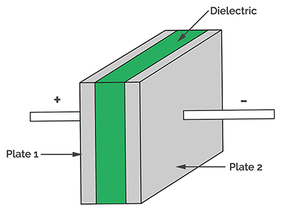
INSIDE A CAPACITOR:
The construction of Capacitor is quite simple. It consists of a two conductive plates like the ones shown in the above diagram ( Plate 1 and Plate 2) where these two plates are separated by a small distance and with insulators in between them also known as Dielectrics. It’s pretty much like a Sandwich where we have two conducting plates and insulating material or Dielectric sandwiched between them.
Each Cap has specific Capacitance to it. We already know that a Capacitor is capable of storing electric charge in its plates. This Capacitance determines the maximum amount of charge it can store. The larger the plates and smaller their distance of separation higher the Capacitance value will be. This Capacitance is given by the formula
where Q is the amount of Charge and V is the voltage applied across it.
FARADS:
So each Capacitor has some Capacitance value in it. The Unit of measurement for Capacitance is measured in Farads. When we specify a Capacitance value as 1 Farad it means that the Capacitor holds charge of 1 Coulomb in its conducting plates when one voltage applied across its terminals.
WORKING OF CAPACITOR:
Now it’s time to dive bit deeper into Capacitor working. As stated above Capacitor acts differently to AC and DC.
CAPACITOR WITH DC:
Let’s consider DC first and see how it reacts to DC. Initially the Capacitor will be in discharged state meaning there will be zero charge across its plates. When DC voltage is applied across its terminals, current flows and charges it. The initial flow of this Charging current through the Capacitor will be very high. This results in Positive charge built up on one plate and Negative on another plate. As the charge across the Capacitor plates increases the charging current gradually gets reduced due to charge accumulation on its plates and it resists the flow of current. Also the charge built up across the plates develop a potential difference of voltage across the plates.
The flow of charging current keeps charging the Capacitor until the voltage developed equals voltage applied across it. At this point the charging current ceases to flow due to the developed voltage across Capacitor. In this instance Capacitor is fully charged with Positive charge in one plate and equivalent Negative charge exists in another. The voltage developed across Capacitor is usually denoted by Vc. Capacitor will hold this voltage Vc until voltage across it exists. Once the voltage supplied stops, discharging current from the Capacitor starts flowing. At this instant Voltage Vc starts dropping and the charge accumulated across its plates reduces.
The discharging current slows down after some point of time at this instant the rate at which voltage drop slows down as well. After some time Capacitor Voltage Vc will reach zero and charge accumulated across it’s plates will be zero. This state is said to be discharged state of a Capacitor. Now you can see the reason why we have compared Capacitor to a battery.
CAPACITOR WITH AC:
As stated earlier Capacitor reacts differently when supplied with AC voltage. When DC voltage is applied Capacitor charges only in one direction. However when AC is applied Capacitor charges and discharges alternatively depending on its frequency. And therefore with AC voltage capacitor will continue to allow current to flow through it indefinitely unlike DC where Capacitor blocks the current after a period of time.
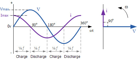
Interesting thing here is charging current and discharging current through a Capacitor when subjected to AC voltage depends on the change of voltage applied across its plates. Current flowing in Capacitor when AC is applied tend to lead the voltage by 90°. Take a look at the below graph.
Consider AC voltage is applied across a Capacitor, initial voltage will be minimum and at this instant charging current will be at maximum as you can see in the above graph. When voltage reaches its peak value charging current will be zero. After reaching the peak value voltage will start to decrease and discharging current starts flowing from the Capacitor as well. When the AC voltage reaches Zero voltage completing the positive half cycle of the signal, discharging current will be at maximum. Once the signal starts with negative cycle discharging current gradually starts reducing and reaches zero once the voltage hits maximum in negative half cycle. Thus we can conclude that Current leads Voltage by 90′ or Voltage lags Current by 90° in AC circuits. This is usually described as the Voltage and Current were in Out of Phase.
CAPACITANCE REACTANCE:
Another key thing to know about Capacitors in AC circuits is that they offers resistance to the Current flow in AC circuits. This is referred to Reactance and more specifically Capacitive Reactance. This Reactance is given by the formula
Xc = 1 / 2πFC or 1 / ωC ( ω = 2πF )
From the above formula we can deduce that Capacitive reactance decrease with increase in Frequency of AC signal and Capacitance of Capacitor. When the signal frequency is high or close to Inifinity, Reactance will be close to zero. Here Capacitor acts like a perfect Conductor. Also when the frequency of AC signal becomes less or close to zero, Reactance will be very high and it acts like a very large resistance or open circuit to the incoming signal.
APPLICATIONS OF CAPACITOR:
Now that we have understood what is a Capacitor and how it works. Let’s jump into the most important section of this article “Applications of Capacitor”.
DECOUPLING CAPACITOR:
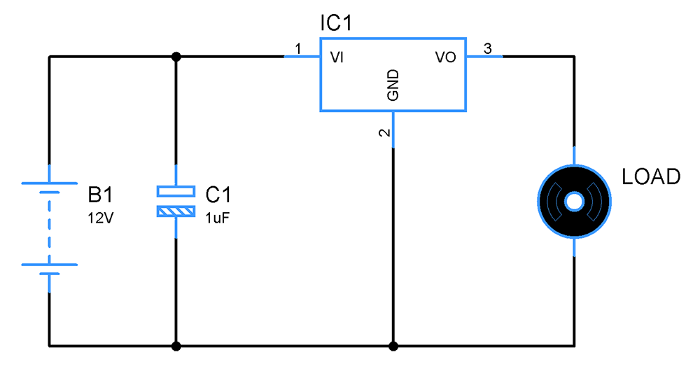
These are Capacitors that is very much important to use in all the digital circuits. Digital IC’s or chips ideally need stable voltage to function. Any spike or voltage fluctuation might lead to non functioning of the chip or sometimes the chip might be destroyed. This is exactly where Decoupling Capacitor will come into play. These are Capacitors that is usually used placed near the chips connecting VCC and GND pins of the chip like shown in the above circuit diagram.
When the circuit is powered ON decoupling Capacitor starts charging via Vcc and stops charging once the Capacitor voltage reaches supplied voltage. At this point when there is fluctuation in supply voltage the Capacitor will provide power to the IC for short period of time to keep voltage to IC stable. Also when there is a spike in input supply voltage Capacitor starts charging to its new supply voltage. This while keeps the voltage input to IC1 stable. In large circuits with many IC’s it’s often advised to use a large Capacitor near the power supply and small Capacitor near to each of the IC used in a circuit. The large Capacitor will provide stable voltage through out the circuit . Small Caps cater the need of IC’s used with it.
COUPLING CAPACITOR:
We have seen Decoupling Capacitors are used to block voltage fluctuations or in other words it helps to block AC signals since fluctuation or voltage drop is a form of AC signal since the voltage of the signal varies over time. Coupling Capacitor on the other hand blocks the DC signal while allowing AC signal to pass through. On other words these Capacitors are used to couple or link AC input signal to next stage of circuit by blocking the undesired DC signals.
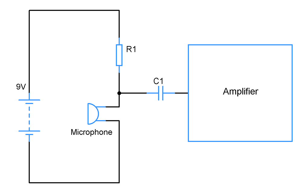
These Capacitors are widely used in Amplifier and Audio applications where our point of interest is only AC signals. Let’s take for example we have an Audio circuit powered by 9v DC supply. The circuit takes voice input from a Microphone and this Voice input ( AC signal ) is our point of interest. There is a huge chance that DC signal from 9v supply might be mixed with this voice input signal. And in order to eliminate this DC element from our Voice input a Coupling Capacitor C1 ( shown in above circuit ) is used where it blocks the DC signal and allows the signal with alternating frequency. Remember we learnt that Capacitor offers very high resistance or blocks the DC signal.
Not only DC, with proper choice of Capacitor values we can successfully block undesired low frequencies and allows only desired high frequencies. This is governed by the Reactance of Capacitor it is given by the formula Xc = 1 / 2πFC ( we have seen this earlier in this tutorial). Remember we already know that Capacitor offers high Reactance to low frequencies whereas for high frequencies Reactance value will be low. Therefore in order to make a Coupling Capacitor allow low frequency signals we need to use Capacitors of higher values and for high frequency signals lower value of Capacitors will suffice.
FILTERS:
These are circuit blocks used to filter unwanted frequencies from input signal. Capacitors form an integral part in constructing filters along with Resistors and Inductors. Filters have extended functionality than Decoupling Capacitors. Basically there are three different type of Filters that you need to be aware of.
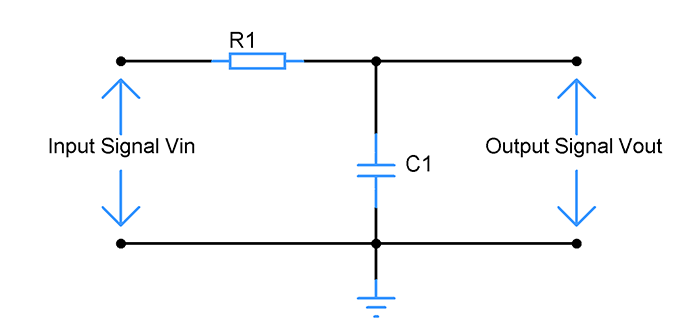
LOW PASS FILTER:
Low pass filters are used to allow frequency components less than cutoff frequency and blocks the frequency components higher than that. Here is how it works when the incoming signal is of low frequency, Capacitor exhibits high reactance ( high resistance ) compared to the resistor. Therefore voltage exhibited across Capacitor will be very high comparing to Voltage drop across Resistor. Therefore we will get the incoming signal without or with low attenuation. Meanwhile when the incoming signal is of high frequency reactance exhibited by Capacitor will be low. So voltage drop at Resistor will be very high comparing to Capacitor voltage thereby blocking the signal from reaching the next stage.
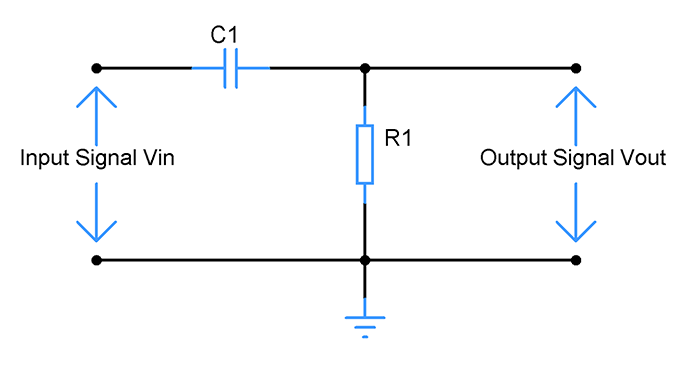
HIGH PASS FILTER:
These are filters which allow only signal of frequencies higher than Cutoff frequency and block signal of lower frequencies. What happens here is when incoming signal is of low frequency Capacitor exhibits high Reactance and acting as a open circuit to the signal. On the other hand when the incoming signal of of high frequency Capacitor exhibits low Reactance ( resistance ). This is very low compared to Resistor R1. Here the voltage drop across Capacitor will be very minimal comparing to Resistor and therefore allowing the high frequency signal output without or low attenuation.
BANDPASS FILTER:
This is a combination of High pass and Low pass filter. This Filter will only allow signal of particular band of frequencies to pass through and blocks the signal outside of this frequency range. This type of filter will ideally have two cutoff frequency Upper and Lower cutoff frequency. This filter will block signal which has frequency lesser than lower Cutoff frequency and greater than Upper cutoff frequency. As you can see in the above circuit it is constructed using High pass and Low pass filters. Combination of these will allow only a band of frequencies between Upper and Lower Cutoff frequencies and blocks signal outside these frequencies.
TIMING CIRCUITS:
From what we have seen so far we know that when using Capacitor with DC it takes time to charge and reach the applied voltage. These timing circuits leverage this characteristic of a Capacitor and use it to generate necessary time delays. But here along with Capacitor a Resistor is used along with it to control the rate of charging of Capacitor which in turn will affect the time delay.
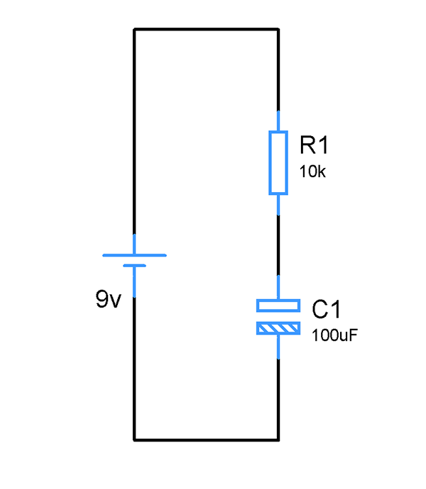
The above shown circuit is a RC timing circuit where Capacitor C1 is supplied with constant DC voltage source of 9v. The time delay generated using this circuit is given by the means of Time constant T. The time constant can be calculated using the formula
T = RC
A Capacitor takes 5T or 5 times of Time constant to be fully charged. So applying the above Resistor and Capacitor value in this equation will yield 5 secs of time delay. Five seconds of time delay for Capacitor to reach supply voltage of 9v across its terminals from the moment power supply is ON.
5T = 5 x R x C
= 5 x 10k x 100uF
Time delay = 5 secs.
Interesting thing happens behind the working of this circuit to generate the required time delay. In order to understand this let’s take a look at the charging curve of a Capacitor graph.
The above graph shows the relation between Voltage, Current and Time taken to charge the Capacitor. At time t = 0 Capacitor will be in discharged state and DC voltage will be applied to the circuit. Once the voltage is applied charging current flows through the Capacitor accumulating equal and opposite charges on the plates. This results in increase of Capacitor Voltage Vc. The charging current will be at maximum when in the beginning. The Capacitor will be charged 63% of supply voltage when time reaches constant T, which is marked 1 in above graph.
Relating this to the above circuit T will be of 1 sec and by that time Capacitor voltage will be 63% of 9v which is 5.67v. And from the graph you can deduce by 5T ( time constant ) the Cap will be charged to its supplied voltage stopped the charging current completely. Now the Capacitor is said to be fully charged.
Using the equation 5T = 5RC , you can fix the values of Capacitor and Resistor to force this RC circuit to generate the required time delay for any application.
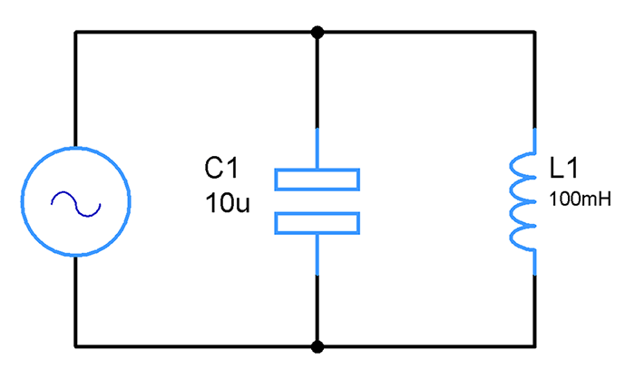
TANK OR TUNED CIRCUITS:
These type of circuit can be mostly found in Radio transmitters, Receivers and frequency selection applications. Capacitor works along with Inductor in these circuits to do the job. Tank or Tuned circuits will be employed when we need to generate a signal or receive a signal of particular frequency from complex signal with multiple frequency components in it and that’s where the word “Tuned” came from. The elements in this circuit C and L can be tuned as per our need.
The working of above circuit is based on Reactance of both Capacitor and Inductor. Like Capacitor, Inductor does exhibit Reactance. But unlike Capacitor Inductor exhibits high reactance to high frequency signals whereas Capacitor exhibits high reactance to low frequency signals. This tank circuit will be constructed in a way where reactance of both the elements Capacitor and Inductor will be equal at a frequency thereby achieving Resonance. At Resonance this tank circuit is capable of generating signals of assigned frequency or receive signals of that frequency.
Here is how it works, when the Capacitor connected in this circuit is charged, it stores the charges between in its plates. The current from Capacitor will then move to Inductor which in turn will build up a magnetic field around it. This results in depletion of charges across the plates and Voltage across its drops to zero. Inductor has the property of resisting change in flow of current through it. Once the current from Capacitor stops, magnetic field of Inductor collapses enabling the current to flow through the circuit. This current reaches the Capacitor and charges it again building charges in its plates and develops voltage across it. This cycle continues to repeat over and over again generating signals of resonant frequency. We can also use this circuit to extract signals of this frequency from a complex signal.
SUMMARY ABOUT CAPACITORS:
Capacitors are constructed using two parallel plates separated by an insulating medium or dielectrics.
Capacitors store energy in the form of electrical charge resulting developing voltage across its plates.
The amount of charge it can store in its plate is determined by its Capacitance value.
It allows DC signal to pass through only for a period of time while allowing AC signal to pass through indefinitely.
It exhibits high reactance ( resistance ) to low frequency signals and low reactance to high frequency signals.
Capacitors are most commonly used in Amplifiers, Filters, Power supplies, Transceivers and so.
That’s pretty much about Capacitor and its working. Hope this tutorial is informative and gave you an idea about about its working and how to use in practical circuits. I would also like to add that there are other applications of Capacitor that we haven’t covered in this tutorial. But I have covered the most important applications here.
We will be publishing tutorial on other components pretty soon. Subscribe to our Newsletter and follow us via Social media channels to get regular updates from our website. If you have any questions regarding Capacitors, do leave them in the comment box below, I will be happy to answer your questions.

 These are filters which allow only signal of frequencies higher than Cutoff frequency and block signal of lower frequencies. What happens here is when incoming signal is of low frequency Capacitor exhibits high Reactance and acting as a open circuit to the signal. On the other hand when the incoming signal of of high frequency Capacitor exhibits low Reactance ( resistance ). This is very low compared to Resistor R1. Here the voltage drop across Capacitor will be very minimal comparing to Resistor and therefore allowing the high frequency signal output without or low attenuation.
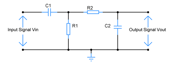
 The above shown circuit is a RC timing circuit where Capacitor C1 is supplied with constant DC voltage source of 9v. The time delay generated using this circuit is given by the means of Time constant T. The time constant can be calculated using the formula
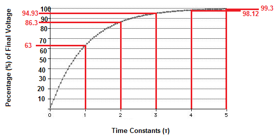


bien explique merci