Interrupts are one of the most used feature in a microcontroller. Interrupts are events that needs immediate attention by the processor/ controller. When an interrupt occurs controller will pause executing the code in its program memory and execute the code that is associated to interrupt. This piece of code is the Interrupt Service Routine ISR. Once ISR is executed the controller will resume execution of instructions in its program memory.
ATtiny85 has a total of 15 interrupts. Most of the interrupts are associated to peripherals like ADC, timer, Serial communication, Analog comparator and so on. These associated interrupts can be configured to execute alongside the operation of these peripherals. Among these interrupts External and Pin change interrupts are not associated with any peripherals instead they are interrupts which is triggered by external events and change of state of Digital I/O pins.
External Interrupt
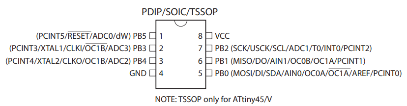
These are interrupts that are triggered by events external to the microcontroller. Events include button press, sensor output or other form of digital inputs. In ATtiny85 manufacturers have assigned the pin PB2 ( INT0 ) to use for external interrupt.
Pin change interrupt
These are interrupts that will be triggered when digital I/O pin change its current state. This pin change interrupt can be attached to any of the six digital pins ( PB0, PB1, PB2, PB3, PB4, PB5 ) of ATtiny85 microcontroller. This pin change can be triggered by I/O pin configured as input and the change of pin state is introduced by external source. In other cases I/O pin can be configured as output and the interrupt will be triggered by the change of state due to user’s code/instructions.
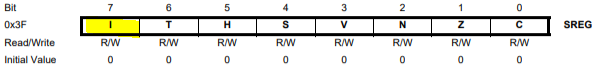
SREG AVR Status register
The bit 7- I is the Global Interrupt Enable which enables the interrupt usage for the Microcontroller.
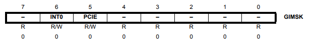
This register contains the bits INT0 and PCIE. Setting the INT0 bit to 1 enables the external interrupt to PB2 ( INT0 ) pin. It is possible to trigger interrupt even if the PB2 is configured as output. This allows the software to trigger external interrupt rather than triggering by an external even itself.
PCIE bit enables the pin change interrupt. Setting the pin enables this interrupt and in addition to this user need to configure the pins they wish to attach this interrupt.
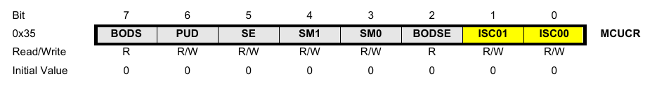
MCUCR – MCU Control Register
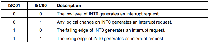
ISC01 and ISC00 bits in MCUCR register is used to configure the point at which an external interrupt should be triggered. The below table lists the corresponding bit combinations and their respective trigger point.
For the purpose of this tutorial we have configured our interrupt to be triggered at falling edge of signal to INT0 pin.
PCMSK : Pin Change Mask Register
The bits PCINT0 to PCINT5 can to attaches the pin change interrupt to ATtiny85 pins PB0 to PB5. For example setting the PCINT0 to 1 will attach pin change interrupt to PB0. Likewise we can attach this interrupt to as many I/O pins as we want. But the important thing to note here is that all of these Pin change interrupts share a single ISR vector address. This implies that even though if you use pin change interrupts on multiple pins, every triggered interrupt will execute the same function. If you wish to establish differentiation between pins, we have to create rules and execute within the ISR routine.
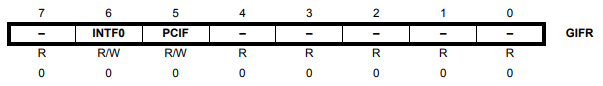
GIFR : General Interrupt Flag Register
This register contains the interrupt flag register for both external and pin change interrupt. This flag bits will be set by hardware when the interrupt occurs. This bit will be cleared when the controller executes the corresponding interrupt service routine ( ISR ).
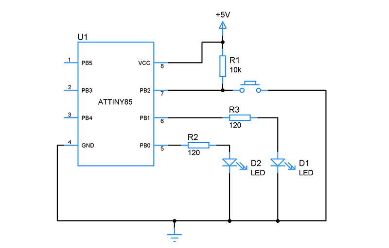
Circuit diagram for External and Pin change interrupt:
In this circuit a button to PB2 ( INT0 ) pin triggers the external interrupt. Upon triggering of external interrupt LED connected to PB1 is made to light up. A pin change interrupt is also attached to pin PB1. The triggered interrupt due to change in state of PB1 will switch toggle LED state in PB0.
Sample code for External and Pin change interrupt:
#include<avr/io.h>

ISR (INT0_vect)        // Interrupt service routine
{
  PORTB ^= (1<<PB1);    // Toggling the PB2 pin
}

ISR (PCINT0_vect)        // Interrupt service routine
{
  PORTB ^= (1<<PB0);    // Toggling the PB2 pin
}


void external_interrupt()
{
  DDRB |= (1<<PB1)|(1<<PB0);     // set PB2 as output(LED)
  sei();     //enabling global interrupt
  GIMSK |= (1<<INT0);     // enabling the INT0 (external interrupt)
  MCUCR |= (1<<ISC01);    // Configuring as falling edge
}

void pin_change_interrupt()
{
  DDRB|=(1<<PB0);
  GIMSK|= (1<<PCIE);
  PCMSK|=(1<<PCINT1);
}

int main()
{
  external_interrupt();
  pin_change_interrupt();
  while(1)
  {

  }
}

 For the purpose of this tutorial we have configured our interrupt to be triggered at falling edge of signal to INT0 pin.
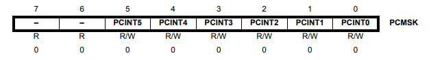


#include should be #include ,
You also forgot #include