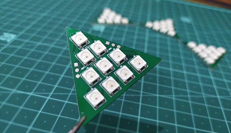
Development boards has allowed us to unleash the creativity within us and as a result you might have seen makers building interesting projects. For the love of LEDs, I had designed a custom PCB which includes 10 Neopixel LEDs. Using that I have built a attractive LED pyramid using WS2812B Addressable RGB LEDs. In this project article we are going to discuss how we can use the very same board Triangle LED board to create another interesting project, a gesture control game using NodeMcu development board and RGB LEDs. This is basically a very simple and interactive LED board game that you can play using different gestures. I have used a gesture sensor along with neopixel LEDs to make this project. It’s a very fun project and I hope you will enjoy making it too.
Physical setup:
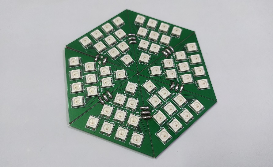
This is the PCB I made here was from my previous LED pyramid project, where a triangular shaped PCB is used. So if we join 6 of them side by side we get a hexagonal LED plate containing 60 LEDs. To control the LEDs and gesture sensor, I have made a custom Pixel LED controller board which can drive these kinds of LEDs. It also has an I2C port which you can utilize to attach different sensors, gesture sensor in this case.
If you would like to know more about this Pixel LED controller board, please let me know in the comments. You can download the Gerber file for this project below.
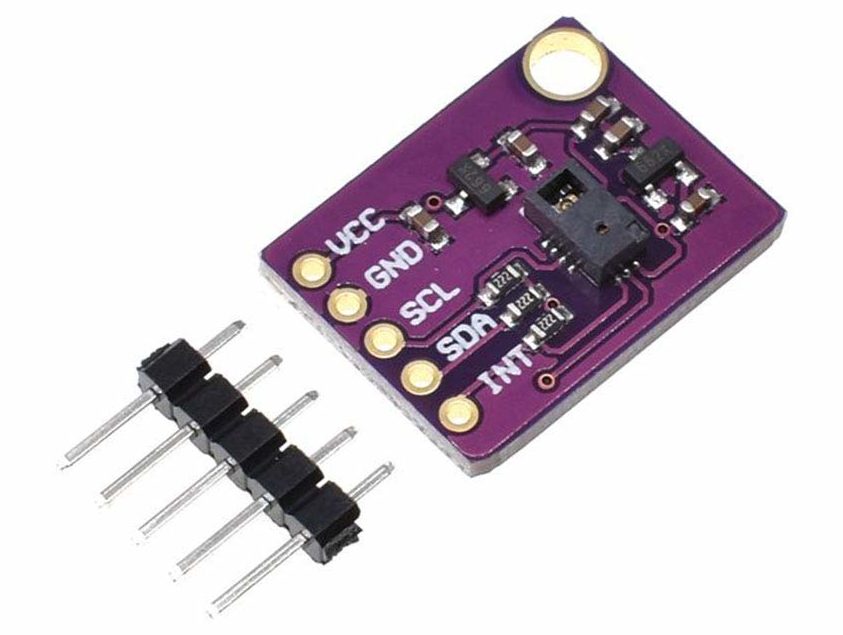
Now the center of the attraction in this project is this PAJ7620 Hand Gesture Sensor. This sensor can detect up to 9 different hand gestures. For only $2 price segment lets see what this sensor has to offer.
The gestures that can be detected are left, right, up, down, forward, backward, clockwise, anticlockwise and waving.
I2C protocol to communicate with the microcontroller.
Detection ranges are from 5-15 cm with 60° angle and 15-30 cm with 30° angle
The working principle of this game is very simple.
After powering it up you have to make a certain gesture which lights up a random LED.
Then you have to remember that LED position and you have to move a LED from start to that position using your gestures.
Once you have reached there you need to perform another gesture which will tell the microcontroller to verify that data with the previous one and if it’s a match you won.
The below video will give you a better idea about the working of this game.
Library required:
Now, to use this sensor we will need to install Gesture_PAJ7620 library by Seeed-Studio in your arduino IDE. You can find this in the library manager of your IDE as well. Along with that you will also need the Adafruit_NeoPixel library by Adafruit for this project.
Code explanation:
#define LED_COUNT 60
#define LED_PIN 2
Here we have defined the total number of LEDs and the LED pin connected to the Microcontroller
randomSeed(analogRead(14));
This function will generate a pseudo-random number with a fairly random input, such as analogRead() on an unconnected pin. Click here to learn more about it.
switch (data) // When different gestures be detected, the variable 'data' will be set to different values by paj7620ReadReg(0x43, 1, &data).
    {
      case GES_RIGHT_FLAG:
        Serial.println("Right");
        right();
        delay(1000);
        break;
      case GES_LEFT_FLAG:
        Serial.println("Left");
        left();
        delay(1000);
        break;
      case GES_UP_FLAG:
        Serial.println("Up");
        up();
        delay(2000);
        break;
      case GES_DOWN_FLAG:
        Serial.println("Down");
        down();
        delay(1000);
        break;
      case GES_CLOCKWISE_FLAG:
        Serial.println("Clockwise");
        clockwise();
        delay(1000);
        break;
      case GES_COUNT_CLOCKWISE_FLAG:
        Serial.println("anti-clockwise");
        anticlockwise();
        delay(1000);
        break;
    }
  }
Here we detect the gesture using the sensor and call a relative function. Which will execute the command defined for that particular gesture.
void left()
{
...
}
If this function is called the MCU starts blinking random LEDs and finally stops at an arbitrary LED. The number of this LED will be stored in the “num” variable. Which will be needed later.
void up()
{
...
}
When this function is called the position of the active LED incremented by one. Similarly when “void down()” function is called the position of the active LED decreases by one. This number will be set by two variables “j” & “k”. In this case the value of “j” is fixed. If “k” increases the LED moves forward and if “k” decreases the LED moves backward.
void clockwise()
{
...
}
This function increments the LED position by 10. Or in this case move the LED from one panel to another. And the “void anticlockwise()” function does the opposite.
void right()
{
...
}
When you reach the targeted LED you need to call this function. This matches the current LED position with the value of the “num” variable. If both the values match then the color of all the LEDs turns to Green or Red if it doesn’t match. You can download the code here.
I hope you liked this gaming project. It will be fun to play with friends and family or at a party. Share it with other if you like this and if you have any queries let us know in the comment section below. Check out other projects in our website.