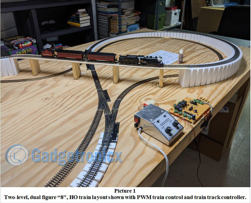
I am a model train buff and have been since I was a kid. Previously I have designed a PWM analog, train speed controller that is also published here on Gadgetronicx. I recently completed a new HO model train track (see Picture 1). It has four switches, two “S” loops, and an overpass bridge that allows for the train to reverse it’s direction. The problem is that switching the switches, reversing the track polarities, allowing for normal reverse control (backing up), and controlling it manually can be complicated and often resulted in wrecks, crashes and derailments. Ouch!
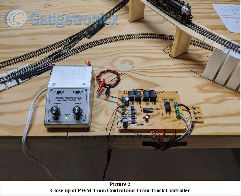
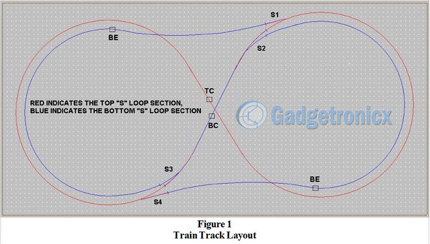
To solve these problems, I needed an automated solution that would handle all of the track switches and track polarity switching automatically. I decided a PIC microcontroller could handle the task easily, so I designed the HO model Train Track Controller unit (see Picture 2). Figure 1 below shows the model train track layout and the magnetic reed switches that are used to detect when the train passes key control points on the layout. The magnetic reed switches are labeled TC, BC, and BE. The two BE switches are wired in parallel to detect the ends of the bottom “S” loop. Switch TC is the center of the top “S” loop. Switch BC is the center of the bottom “S” loop. The top “S” loop and the bottom “S” loop are electrically isolated where switch S1 connects to switch S2 and the end of the bottom “S” loop. Similarly, switch S4 is electrically isolated from switch S3 and the other end of the bottom “S” loop. The two “S” loops combine to form the two-level, dual figure “8” layout design.
Switches S1 and S2 are connected such that when S1 is straight, S2 is curved. When S1 is curved, S2 is straight. The same applies for the switch pair S3 and S4. They are wired in a reversed (crisscrossed) fashion so that energizing one to be curved causes the other to be straight and vice versa. Each switch has a dual solenoid coil to change the switch state. Thus two solenoid drivers were required for each pair of switches. To reverse the track polarity for each “S” loop, two SPDT relays were used to form a DPDT switch. To reduce current draw and insure that no track power was applied when the controller power supply was OFF, the contacts were connected to only allow power to be applied when each pair of relays were oppositely powered.
Model train track controller operation:
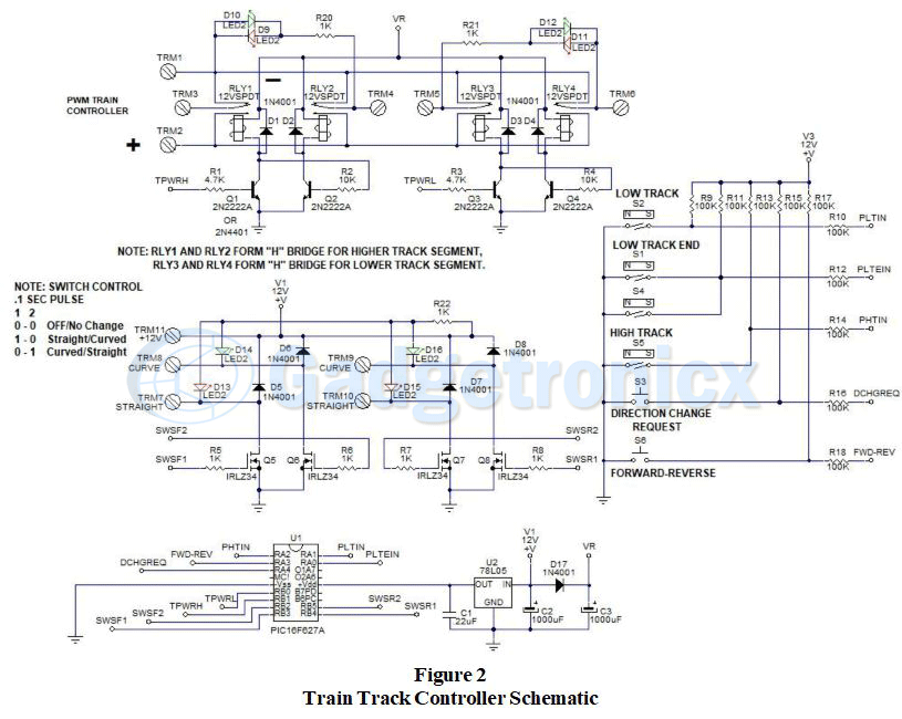
Please refer to the schematic in Figure 2 for the following circuit description. The PIC microcontroller chosen is a PIC16F627A. It has an internal oscillator calibrated at 4 MHz and features up to 14 I/O depending on how it is configured. I prefer to leave PCL (program clock), PDT (program data), MCL (master clear), Vss and Vdd available so that ICSP (In Circuit Serial Programming) can be used to debug the code, or update the firmware with program updates, new features, or bug fixes. This design uses a total of eleven I/O, 5 inputs and 6 outputs, to perform its function. Two inputs are used to request a change in direction of the train on the layout, or to reverse the track polarity on both “S” loops simultaneously to back up the train to couple, or uncouple cars.
The change direction request involves determining the current direction and position of the train, then throwing the appropriate switches and changing the track polarities in a sequential pattern. This is done by the firmware in the PIC. A sequential step sequence program handles this task. Once the change direction request is made, the program looks for the train to pass over either the TC or BC reed switch.
It checks the existing track polarity to determine which way the train is heading. It then commands the correct switches to transfer to opposite states, thereby allowing the train to transfer from the top “S” loop to the bottom “S” loop, or vice versa depending on the direction of the train and whether the TC or BC reed switch was activated. If the TC reed switch initiates the direction change, the program looks for a BE reed switch to be activated to transfer the switches back to their original state. If the BC reed switch initiates the direction change, the program looks for the TC reed switch to be activated to transfer the switches back to their original state. The polarity of the top “S” and bottom “S” loops are changed in sequence to facilitate the direction change.
Here are the steps the program follows:
1. Direction Change Request pressed? If direction is CW, then go to step 2, else go to step 7.
2. If TC activated, go to step 3, or if BC activated, go to step 5, else wait.
3. Set bottom “S” polarity = CCW, set S1, S2 to straight.
4. If BE activated, set top “S” polarity = CCW, set S1 S2 to normal, reset step control to 1.
5. Set top “S” polarity = CCW, set S3, S4 to straight.
6. If TC activated, set bottom “S” polarity = CCW, set S3, S4 to normal, reset step control to 1.
7. If TC activated, go to step 8, or if BC activated, go to step 10, else wait.
8. Set bottom “S” polarity = CW, set S3, S4 to straight.
9. If BE activated, set top “S” polarity = CW, set S3 S4 to normal, reset step control to 1.
10. Set top “S” polarity = CW, set S1, S2 to straight.
11. If TC activated, set bottom “S” polarity = CW, set S1, S2 to normal, reset step control to 1.
The model train track controller circuit uses two transistors to power the SPDT relays. Transistor Q1 and Q2 power relays RLY1 and RLY2 respectively. The base of Q2 is connected via R2 to the output of Q1 and thus acts as an invertor. The same is true for transistors Q3, Q4 and RLY3, RLY4. Therefore only one output from the PIC is required to change the top “S” loop and one output to change the bottom “S” loop polarity. This also means that only two relays are energized at any time.
This reduces the current demand in half. Additionally, if the power to the controller is interrupted, all the relays will be OFF and the track will have the same voltage on all the rails so the train cannot run without the track controller being powered and active. This is a good safety feature.
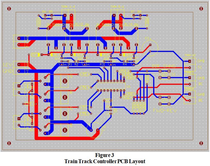
Figure 3 shows the PCB layout for the circuit in Figure 2. To make the unit versatile, screw terminal blocks were used for all of the connections to the board. TRM-1-2 is used to input the PWM speed control output from the Train Controller unit. TRM-11-G is used to connect the board to the auxiliary 12V power supply. This supply should be capable of large current surges when the switch solenoids are activated for .1 seconds. I used a 12V @ 1A DCV wall transformer unit that worked well. Originally I tried using a 12V @ 1A switching power supply, but the internal protection circuitry limited the current surge and the switches would not switch. Sometimes the old school stuff works better in a given application.
The PWM train controller is connected to TRM-1-2 to power the train tracks. TRM-3-4 supply the switched power to the top “S” loop. TRM-5-6 supply the switched power to the bottom “S” loop. When the train is running, the LED’s showing the track polarity should be the same color, green for example when the train is moving from back to front across the top bridge, and red when the train is running in the opposite direction. At this point when the reverse switch is pressed, both LEDs will change to allow the train to back up. When the reverse button is pressed again, the LEDs will switch back to their original color allowing the train to again run forward.
Some other interesting circuit features to note. All of the inputs use a 100K resistor to protect the inputs to the PIC against static discharge, or induced transients from nearby noise sources. All of the inputs use 100K pull-up resistors to simplify the layout and pin assignments to the PIC. Initially D17 and C3 were not in the circuit. They were added because when switches were energized for .1 seconds, the relays would de-energize causing the train to stutter and sometimes derail, or uncouple train cars.
The diode allows C3 to charge and prevents it from discharging when the switches are energized. Capacitor C3 supplies current to the relays during the switching period to maintain their state. When either pair of switches is energized, the GRN LED will flash when the switches are set to straight. When the switches are set back to normal, curved, the RED LED flashes. Lastly, notice that the resistors, R1, R2, for Q1, Q2 and R3, R4, for Q3, Q4 are different values. This is because the PIC supplies 5 volts to Q1 and Q3, but when they are OFF, Q2 and Q4 are connected to 12 volts via the relay coils. Since 5 volts is roughly half of 12 volts R1 and R3 are about half the value of R2 and R4.
The parts are listed in the following BOM. Gerber files have been provided if a PCB is desired. PCBWay provides very good PCB boards at reasonable prices. Also, the source code and programming hex file are available as downloads.
PCB design and Gerber files:
Download the Gerber files, source code for this project below
For those of you that build the project, I would like to know how it turned out. If you have any improvements, or suggestions, please leave a comment. Check out other DIY projects in our website.

 Download the Gerber files, source code for this project below


