RGB LED is one of my favorite thing to play with apart from the fact it is cool, RGB LED’s can give great possibilities and save tons of space in our project design. So I intend to write a simple tutorial on working with RGB LED’s with PWM signal using Arduino.
First of all let’s dive into the types of RGB LEDs. These are common anode and common cathode LEDs. In the following Schematics we can see the differences between them.
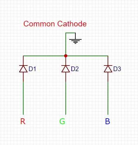
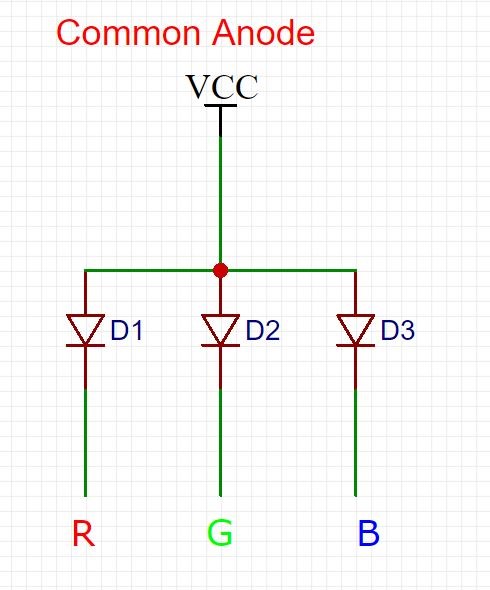
COMMON CATHODE AND COMMON ANODE RGB LED:
The above given diagram shows the internal connection in common cathode RGB LED. Where Red, Green and Blue LED’s are sourced individually using these three pins from a Microcontroller. We can activate these LED’s individually or together, when activating individually LED will emit either Red, Green or Blue. However when operated together we will get a different color apart from these three depends on the combination of these colors. Driving these three pins with PWM signal will produce different color as well as Fading effect.
Here is the internal diagram of Common Anode RGB LED. The main difference between Common Cathode and Common Anode configuration is how the LED’s are sourced. In common Anode configuration LED’s are sourced by power supply such as Vcc. And it is activated by sinking the current via a Microcontroller. So when using RGB LED’s in our project, for common cathode we connect the longest pin to ground and for common anode we connect the longest pin of the RGB LED in our Vcc source voltage.
ADDRESSABLE RGB LED STRIPS WS2812B:
LEDs we have seen above will take three pins from Microcontroller which might be not be possible in all cases. So let’s get into another type of RGB LED’s which is addressable. This only takes one pin and can operate more than one LED’s using that. These RGB LED’s are addressable ( Ex. WS2812B or Single color etc). This types of LEDs has already embedded most of the times the limiting resistors that they need in order to operate. All we need to do is generate a precise PWM signal to drive this LED module and produce the desired color and effect.
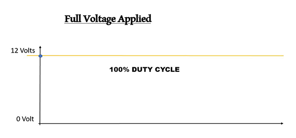
Pulse Width Modulation which is a digital signal operates just like a switch which constantly turns on and off the current of the circuit.The two main factors of PWM are frequency and the duty cycle that we can control both of them through our microcontroller. Frequency determines how fast our PWM signal completes a cycle, and therefore how fast it switches the high (on) and low (off) states.The duty cycle is the amount of time which the signal is in a high (on) state as a percentage of the total time that takes one cycle to be completed. By doing this operation fast enough for our circuit the output will act like a constant voltage which will be provided to our leds as a driving signal. Below graphs will provide a better understanding of PWM.
PWM – 0% Duty cycle
100% Duty cycle
PWM – 50% Duty cycle
OTHER APPLICATIONS OF PWM SIGNAL:
PWM is also widely used in controlling DC Motors speed as well. Also it can be used to control the amount of power delivered to a load without losses that would result in a linear power delivery. Also another use for PWM is in Audio Amplifiers.
DRIVING RGB LED USING ARDUINO:
I have used my Arduino Uno to drive a common Cathode RGB LED where I have connected R, G and B pins to pin 3, 9 and 10 to drive the LED with PWM signal. Below code is adapted from the Example you will find in Arduino IDE “Fading”. Here I have modified this code to fade the RGB LED and change its color.
int ledPin1 = 3;
int ledPin2 = 9;
int ledPin3 = 10;

void setup() {
  // nothing happens in setup
}

void loop() {
  // fade in from min to max in increments of 5 points:
  for (int fadeValue1 = 0 ; fadeValue1 <= 255; fadeValue1 += 5) {
    // sets the value (range from 0 to 255):
    analogWrite(ledPin1, fadeValue1);
    // wait for 30 milliseconds to see the dimming effect
    delay(50);
  }

  // fade out from max to min in increments of 5 points:
  for (int fadeValue1 = 255 ; fadeValue1 >= 0; fadeValue1 -= 5) {
    // sets the value (range from 0 to 255):
    analogWrite(ledPin1, fadeValue1);
    // wait for 30 milliseconds to see the dimming effect
    delay(50);
  }

  // fade in from min to max in increments of 5 points:
  for (int fadeValue2 = 0 ; fadeValue2 <= 255; fadeValue2 += 5) {
    // sets the value (range from 0 to 255):
    analogWrite(ledPin2, fadeValue2);
    // wait for 30 milliseconds to see the dimming effect
    delay(50);
  }

  // fade out from max to min in increments of 5 points:
  for (int fadeValue2 = 255 ; fadeValue2 >= 0; fadeValue2 -= 5) {
    // sets the value (range from 0 to 255):
    analogWrite(ledPin2, fadeValue2);
    // wait for 30 milliseconds to see the dimming effect
    delay(50);
  }

  // fade in from min to max in increments of 5 points:
  for (int fadeValue3 = 0 ; fadeValue3 <= 255; fadeValue3 += 5) {
    // sets the value (range from 0 to 255):
    analogWrite(ledPin3, fadeValue3);
    // wait for 30 milliseconds to see the dimming effect
    delay(50);
  }

  // fade out from max to min in increments of 5 points:
  for (int fadeValue3 = 255 ; fadeValue3 >= 0; fadeValue3 -= 5) {
    // sets the value (range from 0 to 255):
    analogWrite(ledPin3, fadeValue3);
    // wait for 30 milliseconds to see the dimming effect
    delay(50);
  }
}
EXPLANATION VIDEO:
I have made a video explaining this tutorial better.
I hope this tutorial would have helped you to understand RGB LEDs and how to drive them using Arduino. Do post your feedback and queries below. Thanks for reading 🙂


wow nice exeplanation