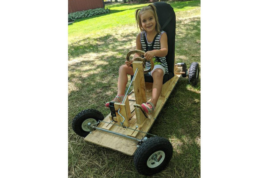
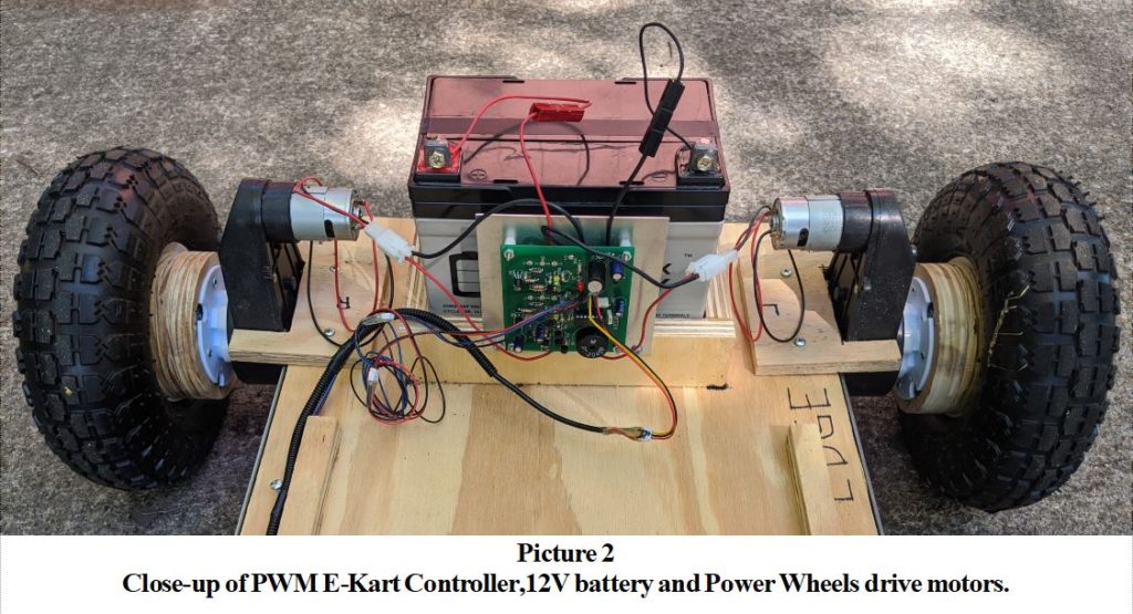
Years ago, I designed a PWM motor controller that I used in a dual, four quadrant, wheel chair control. I called it the People Mover. It was built primarily as a technology demonstrator for prospective engineering clients. When my grand children were old enough, I wanted to build an Electric Go Kart, for them. This will also make a great Electronics project to build for Engineering students. So I designed a PWM controller circuit that could operate two, 12 volt, power wheels drive units, to propel this E-Kart. see Picture 1 and Picture 2. There were several design considerations that had to be incorporated into the circuit design. They are as follows :
Design considerations for Electric Go Kart:
It needs to operate in both forward and reverse modes.
When changing from forward to reverse, or reverse to forward, a two second delay is needed to allow the wheels to stop and avoid overloading the DC motors.
When in the reverse mode, a piezo electric beeper, provides an audible, back-up signal to alert both the driver and pedestrians around the vehicle.
It needs an E-Brake to override all inputs and provide a shorted, motor commutator to electronically brake the vehicle quickly.
A further safety consideration was to wire the brake switch so that an open circuit, when brake was applied, or a broken wire, would cause the brake to be ON and disable the E-Kart from moving.
Similarly, when the forward reverse switch wire is broken, the controller operates only in the forward direction so that it can be driven home.
The magnetic, Hall-effect accelerator pedal puts out about .5 volts (OFF, stopped) to 4.5 volts (100% ON, full speed). This needed to be accounted for in the firmware to provide proper pedal operation.
Electric Go kart ( E-kart ) circuit design:
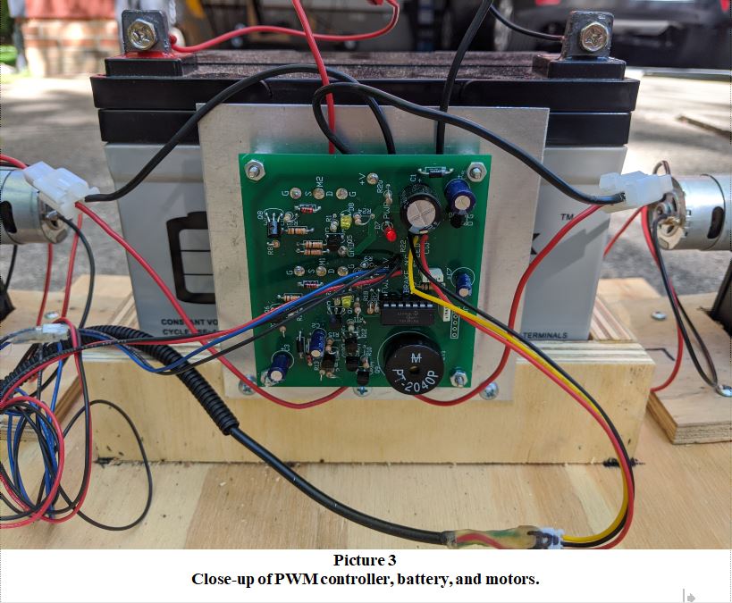
To execute the design, I decided a PIC microcontroller could handle the task easily. I designed and built the E-Kart PWM Controller unit (see Picture 3).
Controller Operation and Circuit Description:
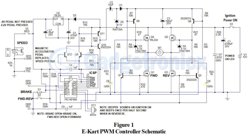
Please refer to the above schematic in Figure 1 for the following hardware circuit description. The PIC microcontroller chosen is a PIC16F684. It has an internal oscillator calibrated at 8 MHz and features up to 12 I/O depending on how it is configured. I prefer to leave PCL (program clock), PDT (program data), MCL (master clear), Vss and Vdd available so that ICSP (In Circuit Serial Programming) can be used to debug the code, or update the firmware with program updates, new features, or bug fixes.
This design uses a total of seven I/O, 3 inputs and 5 outputs, to perform its function. Two inputs are used for the brake and the forward-reverse switches.
Speed control:
The third input is used as an analog input to the PIC’s A/D. The accelerator pedal signal as previously described, is an analog signal that varies from .5 volts (OFF, stopped) to 4.5 volts (ON, 100% PWM, full speed). The 10-bit A/D measures the accelerator input signal. Only the eight MSB’s are used.
To maximize the number of PWM speed steps and minimize program complexity, a number of bits are subtracted to yield 0% PWM below a prescribed input voltage level. To reduce noise, a two-level FIFO buffer averages the input voltage value. After the minimum bits are subtracted, the remaining bits are divided by 4 to yield the PWM steps in a 500 micro-second time frame window. Thus, the PWM frequency is 2 KHz, In 64 discrete PWM speed steps.
Forward drive:
The motors are driven by an “H” bridge comprised of Q1, Q2, Q3 and Q4. In the forward mode, the PIC outputs the PWM signal from pin RC2, to Q1, and Q7 via R12and R2. Transistor Q7 via R3, turns ON Q8 that then turns ON Q2 via R21. Current runs through Q2, the motor, and Q1 to ground. This causes the motors to run in the forward direction.
Reverse drive:
In the reverse mode, the PIC outputs the PWM signal from pin RC3, to Q2, and Q5 via R9 and R1. Transistor Q5 via R4, turns ON Q6 that then turns ON Q4 via R19. Current runs through Q4, the motor, and Q3 to ground. This causes the motors to run in the reverse direction. When the brake is ON, both PIC PWM signal. pins, RC2 and RC3, are held high, ON. Since the emitter of Q5 is connected to RC2 and the emitter of Q7 is connected to RC3, and both PWM pins are high, this causes both Q5 and Q7 to be OFF. Thus Q8, Q2, Q6, and Q4 are all OFF, However, Q1 and Q3 are ON and short the commutator of the motor to provide the electronic braking needed to stop the vehicle quickly.
Transistors Q9, Q10, Q11 and Q12, C2, D1, D5, form a level shifter capacitor charge pump to boost the voltage to 8.4 volts above the twelve volt battery voltage. This voltage is stored on capacitor C3 and is used to bias the high side MOSFETs when they are turned ON. Diodes D3 and D4 protect the gates of the high side MOSFETs Q4 and Q2 respectively. The PIC delivers a 2 KHz square wave signal from pin RA2 to enable the charge pump.
Normally closed switch S1 is used for the brake. Normally open switch S2 is used to select the forward or reverse direction. Regulator U2, steps down the 12 volt battery voltage to 5 volts to operate the PIC, U1, and its related circuitry. LED D7 shows when the power from the 12V battery is ON. LED D7 shows the relative PWM power being supplied to the motors in the forward direction, while LED D8 shows the relative PWM motor power supplied in the reverse direction.
Other key features to note:
The two switch inputs use 100K pull-up resistors to simplify the layout and pin assignments to the PIC. The “back-up” annunciator PZ1 has a resonate frequency of 4KHz. To power PZ1, when in reverse, a 4 KHz square wave is provided by the PIC at pins RC0 and RC1 which are driven 180 degrees out of phase. This increases the volume output.
Electric go kart setup:
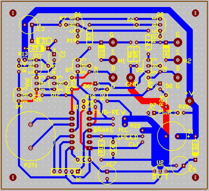
Figure 2 shows the PCB layout for the circuit in Figure 1. To make the unit easy to connect, a combination of headers and plugs were used for all of the connections to the board. The motors used 2-pin locking connectors. The battery power is connected by two individual high power connectors. The switches and accelerator pedal are connected via miniature 2-pin and 3-pin locking connectors. All of the connectors are attached to the PCB with wires. Hot melt glue was used to insulate and provide strain relief for the miniature pin connectors.
PCB design of Electric go kart controller:
The parts are listed in the following BOM. Gerber files have been provided if a PCB is desired. Also, the source code and programming hex file are available as downloads below.
Download Gerber, Source code files and hex programming file:
For those of you that build the project, I would like to know how it turned out. If you have any improvements, or suggestions, please leave a comment. Check out other Projects in our website.
I have an electric wheelchair that I would think could work for making an electric go kart. I would like to sell it cheaply if someone is interested. It is a working multi functional chair. If there is anyone interested in it send me an email.
Hi Steve, I don’t suppose you still have the electric wheelchair for parts? If you do I’m keen to buy it as I’m building an electric gokart for my 6yo daughter
Indeed!! Q12 should be connected to ground, not to +5 volts. The revised schematic has been sent to Gadgetronicx and will be corrected shortly. The error happened during an update. Thanks for your feedback and keen eye. Transistors Q9,Q10,Q11,Q12, diodes D1,D5, and capacitors C2,C3 form a charge pump to raise the gate drive rail for the two, upper “H” bridge MOSFETS about 8.5 volts above the +12 volt battery voltage to enable the same N-channel MOSFETS to be used for the “H” bridge. If any other explanations are required, please let me know. Thanks. Ron Hoffman
This circuit was designed for 12 volt operation only. I have a new circuit being tested which will work with motors up to 2 HP (horse power) and will work with 12, 24, 36, or 48 volt batteries, (1, 2, 3, or 4, 12 volt batteries in series @ 30 A). So check back for that design. Also, I use MPLAB-X IDE and write the code in PIC assembler. This runs the fastest with the least amount of memory. It also provides the best way to debug the code. I use right side comments to describe function and variables which is necessary by ANSI standards to follow the codes opeation. Check out the code provide with the go cart article.

 The parts are listed in the following BOM. Gerber files have been provided if a PCB is desired. Also, the source code and programming hex file are available as downloads below.


Next on the agenda: electronic differential!
I have an electric wheelchair that I would think could work for making an electric go kart. I would like to sell it cheaply if someone is interested. It is a working multi functional chair. If there is anyone interested in it send me an email.
Hi Steve, I don’t suppose you still have the electric wheelchair for parts? If you do I’m keen to buy it as I’m building an electric gokart for my 6yo daughter
Indeed!! Q12 should be connected to ground, not to +5 volts. The revised schematic has been sent to Gadgetronicx and will be corrected shortly. The error happened during an update. Thanks for your feedback and keen eye. Transistors Q9,Q10,Q11,Q12, diodes D1,D5, and capacitors C2,C3 form a charge pump to raise the gate drive rail for the two, upper “H” bridge MOSFETS about 8.5 volts above the +12 volt battery voltage to enable the same N-channel MOSFETS to be used for the “H” bridge. If any other explanations are required, please let me know. Thanks. Ron Hoffman
Can this circuit work with a 24V DC motor using two 12V batteries in series and also what software did you use to code the PIC. Thanks!
This circuit was designed for 12 volt operation only. I have a new circuit being tested which will work with motors up to 2 HP (horse power) and will work with 12, 24, 36, or 48 volt batteries, (1, 2, 3, or 4, 12 volt batteries in series @ 30 A). So check back for that design. Also, I use MPLAB-X IDE and write the code in PIC assembler. This runs the fastest with the least amount of memory. It also provides the best way to debug the code. I use right side comments to describe function and variables which is necessary by ANSI standards to follow the codes opeation. Check out the code provide with the go cart article.
Hello Mr. Ron Offman. Thank you for your design and sharing. Is your electronic circuit design strong enough to support an adult?
Schematic errror: Q12 emitter should be grounded not tied to +5V.
The PCB traces are correct.