Have you ever thought it would be great if you know which part of your room will get the best WiFi signal reception. If yes, this project will be very helpful for you. Nowadays for most of our daily tasks we often rely on WiFi router to connect to the internet be it home or workplace. If WiFi router is placed far from us, we will face connectivity issues due to weak signal strength. As a solution to this I have designed a WiFi strength indicator that can measure WiFi signal strength and display that to us in real time.
COMPONENTS REQUIRED:
ESP8266 :
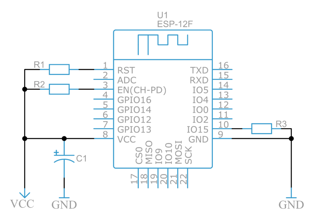
The heart of this WiFi strength indicator project uses popular ESP8266 microcontroller. It has built in WiFi and it’s very cheap, easily available in the market. Also you can use any of its breakout versions such as NodeMCU or Wemos D1 mini as well. If you prefer using bare ESP8266 like me then you will need some passive components such as 10k ohm resistor, 10uf Capacitor etc. ESP8266 works on 3.3v so you will also need AMS1117 3.3v voltage regulator to run this module on 5v. Follow the bare minimum schematic to build usable version of ESP866 for our project. In this project we will use GPIO14 or pin 5 to connect to WS2812B LED strings.
Schematic 1 – ESP-12F
WS2812B LEDs :
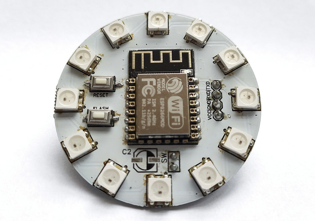
We need to visualize the data, for that we could use any kind of LED or LCD displays. But to give this project a cool look I have used WS2812B individually addressable RGB LEDs. These are also known as Neopixel LEDs. These LEDs are individually addressable, which means we can control many of such LEDs in series using only one pin from Microcontroller. I have connected the LEDs in a circular format to create a ring like formation. The ring type Neopixel rings are also available in the market, you can use that as well.
WS2812B WITH ESP8266:
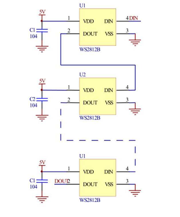
Schematic 2: WS2812B LEDs
Upon referring datasheet of WS2812B LED you will find a standard schematic for connecting LEDs. The VCC and GND pin will be connected to 5V and GND respectively. The DOUT pin or Data OUT pin of first LED will connect to DIN pin or Data IN pin of second LED. In this way LEDs will eventually make a daisy chain formation. Now the DIN pin of first LED will connect to any GPIO pin of Microcontroller or Pin 5 of ESP8266 in that case.
PCB :
I have designed my custom PCB using EasyEDA and ordered it via JLCPCB. The above image shows the assembled PCB of this project. You can download Gerber file for this project below.
Gerber file of WiFi range detector project using ESP8266 modules
Author:
Sayantan
Platforms:
Windows 8
Category:
PCB design
License:
Freeware
Date:
March 3, 2020
PROGRAMMING FOR WiFi STRENGTH INDICATOR:
That’s all we need for the hardware section, so now let’s move onto coding part of it.
Test code: Download the ESP_Signal_Strength_test code from my github repository.
WiFi RSSI: To get the signal strength data we will use WiFi RSSI function. In this code you need to change only the SSID and PASSWORD of your router and hit upload. Once you upload the code to ESP8266, open up the serial monitor and you will see the signal strength in dBm. The higher the RSSI value, stronger the signal will be.
Note that, you will get negative value in the serial monitor. So lower the number better the signal reception.
Adafruit_NeoPixel: We also need Adafruit_NeoPixel library to run the NeoPixel LEDs so download and install this library in your Arduino IDE. In this code, first we have included Adafruit Neopixel library and standard ESP8266WiFi library.
Pin Definition: We have to define the Pin number LEDs need to be connected and the total number of LEDs in the daisy chain. In our case it’s GPIO14 of ESP8266 and 12 LEDs in our case.
WiFi Credentials: Next you need to define the SSID and the PASSWORD of your WiFi router.
Signal Strength Limits: We have to define the Minimum and maximum value of signal strength. Change these values if required.
LED Integration: Now all is left to do is to take that value and map it from 0 to 11 because we have 12 LEDs. This way we have assigned LEDs, mapped signal strength values and defined their respective colors as well. You can change the colors as per your choice.
WORKING VIDEO:
AND IT’S DONE:
That’s the changes you have to do in this code. Save and upload it to ESP8266 module. Once done you can see the signal strength of your router represented by RGB leds.
Hope this project is interesting and will help you with the WiFi issues. Share this project in Social media and other channels and follow our website for more of these projects.We publish new projects and circuits every Wednesday. If you have any queries/ feedback/ suggestions please then let us know in the comment section below. Check out other IOT projects in our website.
Hi. Could you please upload your EasyEDA project file? I want to build your project (thank you for sharing) but want to do small modifications. It would be great, thank you in advance!
Patrick
Hi Patrick,
The schematic design is given in the article there are two parts to it. One is the MCU which is the ESP-12F ( schematic 1) and discrete components connected to it. From pin 5 or GPIO14 we need to connect the string of WS2812B LEDs (shown in schematic 2). Pin 5 of ESP-12F connects to DIN pin of first WS2812B and it sequentially connects to other LED strings. However in schematic 2 it shows 3 WS2812B led’s however in our actual project we have used 12 WS2812B’s. These are skipped for the sake of simplicity of the schematic.
Hi Patrick,
Those capacitors serves as decouplers which will remove any voltage spikes or any fluctuations from 5v source. The 104 marked near the capacitor was referring to part number which is equivalent to 100nF. So both schematics are correct.
Yes you can power the entire circuit using 3.7 Li battery since ESP-12F operates in 3 to 3.6v and WS2812B’s operating voltage is 3.5 to 5v . But ensure your battery is capable of handling the current consumption of the circuit.


Hi. Could you please upload your EasyEDA project file? I want to build your project (thank you for sharing) but want to do small modifications. It would be great, thank you in advance!
Patrick
Hi Patrick,
Here is the project link – https://easyeda.com/Sayantan98/espring Hope it helps.
Hi Frank,
Thank you very much!!
Regards
Patrick
I am new in this, so I found out a Schematic would be helpful, on the link you mentioned there is only the PCB. Any plans to upload this?
Thank you in advance!
Best regards
Patrick
Hi Patrick,
The schematic design is given in the article there are two parts to it. One is the MCU which is the ESP-12F ( schematic 1) and discrete components connected to it. From pin 5 or GPIO14 we need to connect the string of WS2812B LEDs (shown in schematic 2). Pin 5 of ESP-12F connects to DIN pin of first WS2812B and it sequentially connects to other LED strings. However in schematic 2 it shows 3 WS2812B led’s however in our actual project we have used 12 WS2812B’s. These are skipped for the sake of simplicity of the schematic.
Hi Frank,
Thank you, this was clear, but for me it’s not clear how u choose the capacitors. I found a similar circuit from wemos with their LED shield and they used 100nF on each LED (https://www.wemos.cc/en/latest/_static/files/sch_rgb_led_v1.0.0.pdf).
If I want to use 3.7V Li-Battery, can you recommend any 5V voltage Regulator? And can your voltage Regulator AMS1117 connected after the first 5V one? Found also this https://www.wemos.cc/en/latest/_static/files/sch_battery_v1.3.0.pdf
Hi Patrick,
Those capacitors serves as decouplers which will remove any voltage spikes or any fluctuations from 5v source. The 104 marked near the capacitor was referring to part number which is equivalent to 100nF. So both schematics are correct.
Yes you can power the entire circuit using 3.7 Li battery since ESP-12F operates in 3 to 3.6v and WS2812B’s operating voltage is 3.5 to 5v . But ensure your battery is capable of handling the current consumption of the circuit.
Hope this helps