Whether you are just practicing at home, recording songs for friends, or playing at an open mic night, this equalizer-mixer is a great addition to your sound gear. It has many great features you won’t find on low-cost mixers. The 4-channel, 2-band mixer features:
Phantom power for electret microphones.
Selectable dual input gain (2.5X or 20X) on each channel.
Runs on a DC battery, or input voltage supplies from 9V to 12v.
Has two dual mono outputs for:
An amplifier input.
Post mixer sound effects.
Recording board inputs
An audio amplifier monitor input.
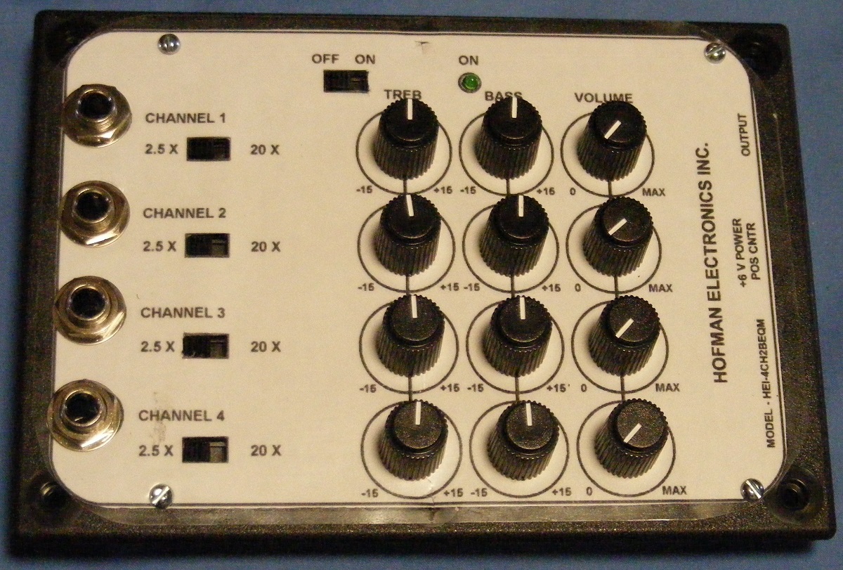
4-Channel,2-Band Equalizer-Mixer
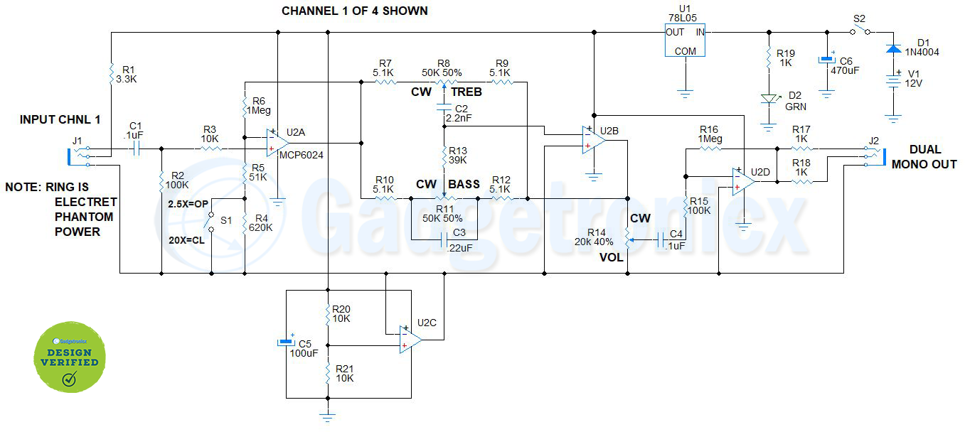
The unit uses two, quad, Rail-to-Rail Input-Output (RRIO) op-amps, (Microchip Technology MCP6024), and one dual, RRIO op-amp, (Microchip MCP6022). The schematic in Figure 1 is used for the discussion of the operation of the mixer. Only one channel is shown for reasons of clarity.
Circuit diagram and Working explanation:
U2C and U2D are part of the dual op-amp, Microchip Technology MCP6022. U2C is connected as a unity gain buffer and provides the common, or pseudo ground reference of 2.5 volts, to all of the other op-amps and input and output grounds. U2D is the inverting mixer which accepts the input from all four channels via each channel’s volume control (R14), bypass capacitor (C4) and input resistor (R15). Resistor R16 (1Meg), R15 (100K), and U2D form an inverter with a gain of 10. The output of U2D is connected to the stereo output jack J2 via two 1K resistors (R17, R18). Two output signals are thus provided for a power amplifier, a recording input, post mixer effects processing, or a monitor amplifier input as previously listed.
Figure 1
In order to preserve the same phase of signals at the output, the channels have one inverting stage. A signal is input into J1 with either a quarter inch, mono or stereo phone plug. If the input is an unbalanced high impedance microphone, a mono plug is used. If an electret microphone is used and requires phantom power, a stereo plug is used. The ring on the stereo plug brings the phantom power to the electret microphone and the signal is fed to the tip of the stereo plug.
Treble, Bass and Volume controls:
The audio signal is input to C1 which isolates any DC voltage and passes the signal through R3 to the +input of U2A. Resistor R2 (100K) is provided as an input load and a ground reference for U2A. U2A acts as a non inverting input buffer with selectable gain. Resistors R4, R5, and R6 form the feedback gain for U2A. When switch S1 is open, the gain is G = 1 + (1Meg / 51K + 620k) = 2.5 (low gain). When switch S1 is closed, the gain is G = 1 + (1Meg / 51K) = 20 (high gain). At this point, the signal is in phase with the input signal. It is passed to the dual band pass filter (Treble and Bass) controls and their associated components.
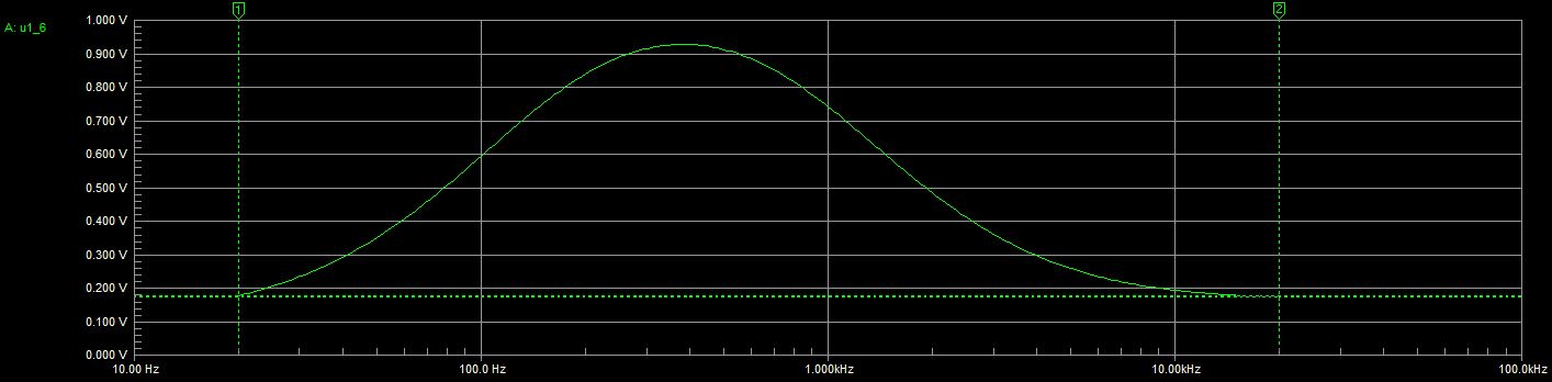
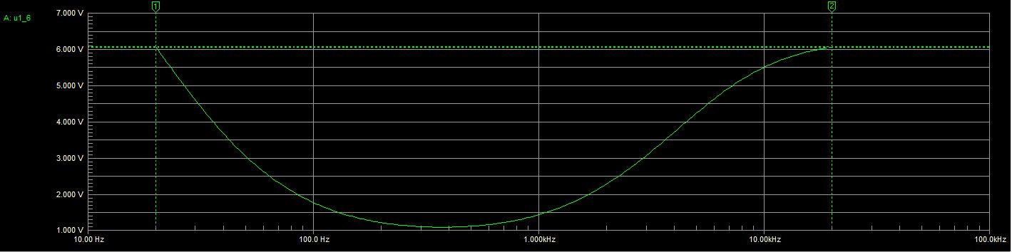
The common feed point of the filter network connects to the -input of U2B. This means that the output of U2B is 180 degrees out of phase with the input signal. When it is inverted 180 degrees again by the mixer (U2D), the output is then in phase with the input signal. The BASS control has a corner frequency of f = 1 / (2pi * 5K * 220nF) = 150Hz. If more BASS boost, or cut is desired, C3 can be reduced to .15uF (210Hz). The TREBLE control has a corner frequency of f = 1 / (2pi * 41K * 2.2nF) = 1800Hz. The cut and boost curves are shown in Figure 2 and Figure 3 respectively.
Figure 2
Figure 3
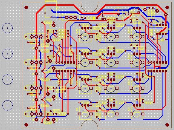
PCB design:
Figure 4 shows the PCB layout for the EQ-Mixer. The circles with dots to the left are the locations for the quarter inch stereo phone jacks. The Gerber file for mid level1 is for machining only and is not included in the PCB zip file.
Figure 4
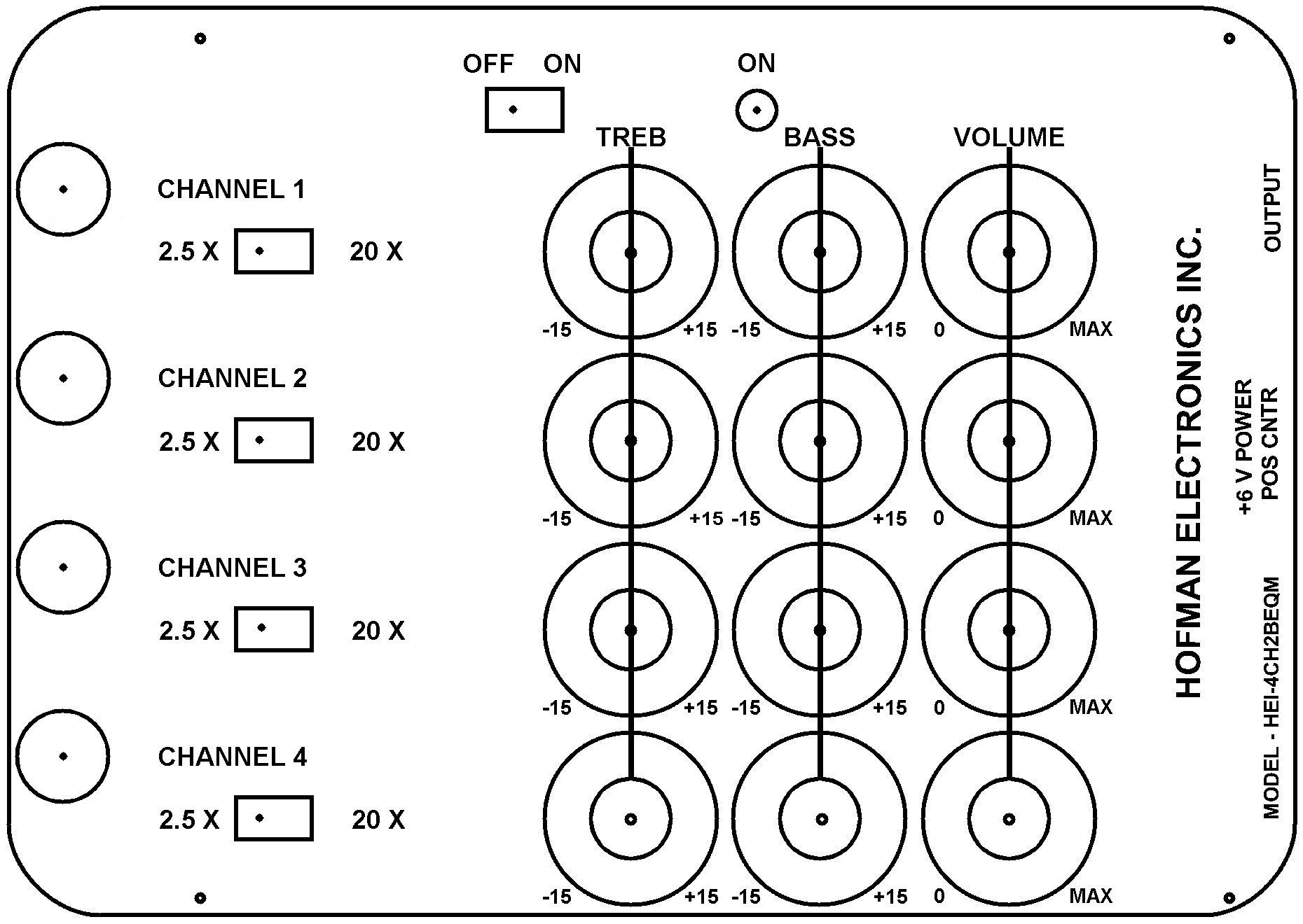
The label file, shown in Figure 5, can be printed twice and used as a machining template and the final label. I laminated it with Fellow’s clear adhesive sheets. The following size drills were used to machine holes in the enclosure.
Use a 7/16″ (12mm) drill for the four 1/4 inch phone jacks.
A 9/64″ (4mm) drill for the LED
A 11/64″ (4.5mm) drill for the five switches
A 19/64″ (8mm) drill for the tone and volume controls
A 1/8″ (3.2mm) drill for mounting the PCB board
Figure 5
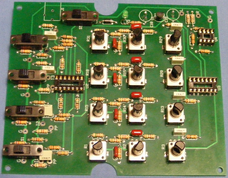
Assembled Equalizer:
The below Figure shows the PCB board loaded with components.
Figure 6
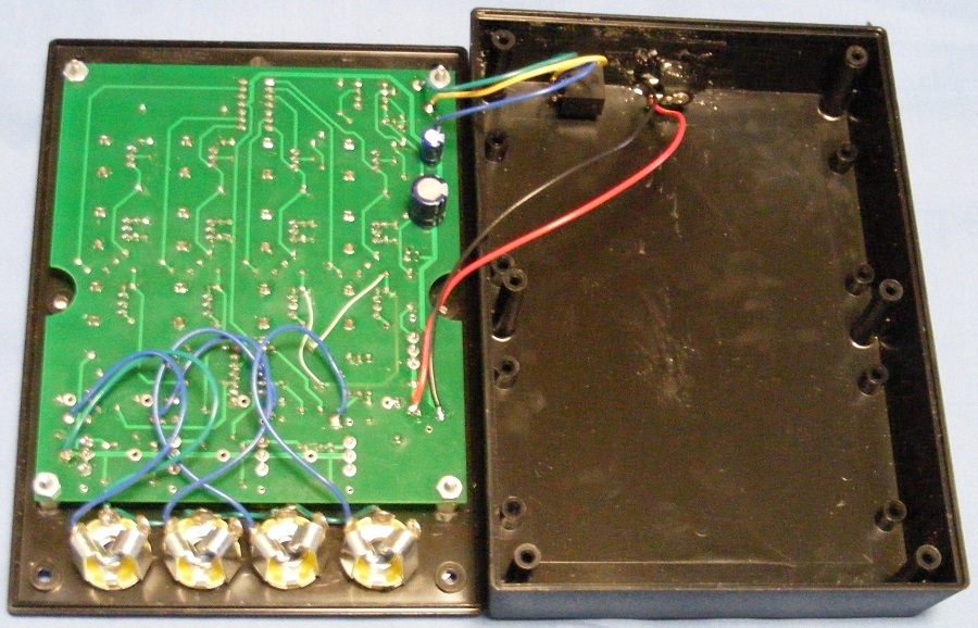
Figure 7 shows the assembly before closing it up.
Figure 7
This unit works really well. I have had several requests from friends, guitar students, and admirers at open mics to make them units. Hope you have fun building and using the 4-channel, 2-band EQ mixer.
Bill Of Materials (BOM) Listing
ITEM
QTY
REF
DESCRIPTION
1
4
C1
0.1 uF metalized film capacitor
2
4
C2
2.2 nF metalized film capacitor
3
4
C3
220 nF metalized film capacitor
4
4
C4
100 nF metalized film capacitor
5
1
C5
100 uF, 16V, aluminum electrolytic capacitor
6
1
C6
470 uF, 16V, aluminum electrolytic capacitor
7
1
D11
GRN LED
8
4
R1
3.3K 1/4W 5% carbon film resistor
9
5
R2, R15
100K 1/4W 5% carbon film resistor
10
6
R3, R20, R21
10K 1/4W 5% carbon film resistor
11
4
R4
620k 1/4W 5% carbon film resistor
12
4
R5
51k 1/4W 5% carbon film resistor
13
5
R6, R16
1Meg 1/4W 5% carbon film resistor
14
12
R7, R9, R10, R12
5.1K 1/4W carbon film resistor 10K potentiometer
15
4
R13
39K, 1/4W 5% carbon film resistor
16
8
R8, R11
50K linear potentiometer, Bourns PTV09A-4020F-B503
17
4
R14
20K audio potentiometer, Bourns PTV09A-4020F-A203
18
3
R17, R18, R19
1K 1/4W 5% carbon film resistor
19
5
S1, S2
SPDT mini slide switch, ALL ELECTRONICS SSW-91
20
2
U1A-D, U2A-D
MCP6024, quad op-amp, Microchip Technology
21
1
U3A-B
MCP6022, dual op-amp, Microchip Technology
22
1
U2
78L05, 5 V regulator
23
4
J1
1/4 inch, stereo phone jack.
24
1
J2
1/8 inch stereo phone jack
25
1
J1
2.1 x 5.5 mm coaxial power jack
26
1
V2
6-“AA” or “AAA” battery holder and batteries (optional)
27
1
P1
2.1 x 5.5 mm coaxial power plug.
28
1
V2
9 – 12 Volt, 1A or 2A, power supply, center positive
29
1
ENCL
Serpac SR072B, 6.88″ x 4.88″ x 1.46″ black ABS enclosure
Gerber files:
You can download the gerber files of this PCB below. You can use PCB manufacturing services like JLCPCB to get this PCB unit manufactured.
Hope this project will spoil your neighbor’s sleep but have fun anyways (just kidding). If you have any questions or help related to this project do post them below in the comment box. Check out other Electronics projects and Circuits in our website.