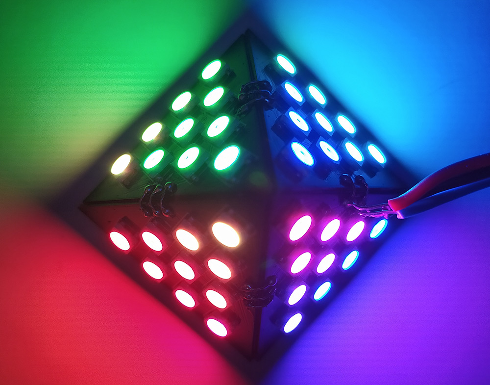
I always had this crazy idea of making a 3D object using PCBs. Yes, the very same Printed Circuit Board that we use in various projects. All it takes is being good at designing PCBs and lot of creativity. In this article, I am going to take you through step instructions on making this LED pyramid. By following these steps you can make one for yourself well.
PLANNING FOR LED PYRAMID:
The first step for this project is to decide what we are going to make and how! My initial plan is to make a PCB Cube, but that’s a very basic 3D structure. Also some other makers ( Instagram: indoorgeek & maker moekoe ) already made their version of cube. So I decided to make something else, like a Pyramid! You can choose any other Shapes. Its up to your creativity and imagination. Now a square has 4 faces, so our LED pyramid need 4 PCBs to cover each side.
DESIGN:
Designing PCB’s was quite a challenge. First I have created the border layout. I made an equilateral triangle of 45mm. Then I place 10 WS2812B LEDs on the top side of PCB with input pads on one side and output pads on the other side of the PCB. Check out the below circuit diagram to see how to chain WS2812B LEDs together as per our need.
Now, we need a microcontroller to run the LEDs. Here any microcontroller would work just fine, like Atmega328p or even a Attiny85. But I wanted to have more control LEDs and want to control the LED effects using my smartphone, so I decided to use an ESP-12F WiFi module which uses ESP8266 controller and gives the WiFi connectivity feature to this project. I have added this MCU and some passive components associated with it in the back side of the PCB.
I have connected the Data Input pin of the fist LED to GPIO2 pin of ESP-12F module. Here I have used 10×4 =40 pcs of WS2812B LEDs. Now each LEDs consumes about 50mA of current So At full brightness this thing can draw about 2000mA or 2A of current.
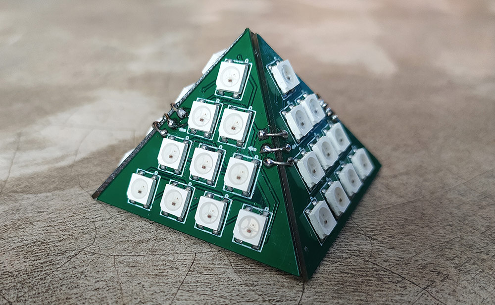
I got the PCB ordered from PCBway. First solder all RGB LEDs on front side of the PCB. I did the same for 3 more PCBs as well. Then I solder the ESP-12F, SMD capacitors and resistors on the back side of PCB. We will is to do this for only one board and other three boards only has LEDs. These 4 boards will be connected to one another using the connector placed on sides of each boards. If you need some tips about SMD soldering, here is some tips and techniques.
CODE:
I have used the WS2812FX library for controlling the LEDs. And since we have WiFi support on board, I have integrated Blynk IOT Platform in this project. This will allow me make a nice user interface for changing the effects and create some custom animations of my own. You can download the code from my github for this project. In the code all you have to do is to change the Blynk authentication code, which will be sent to your email address after creating a new project. And the SSID and Password of your router.
BLYNK:
Let ‘s move on to the App section of this project.
In the Blynk app, first we need to create a new project and give it a name.
Then we need to select the device type to ESP8266 and click the create button.
At this point you will have the authentication key for this project and you will come to the dashboard page.
Here you need to select some widgets.
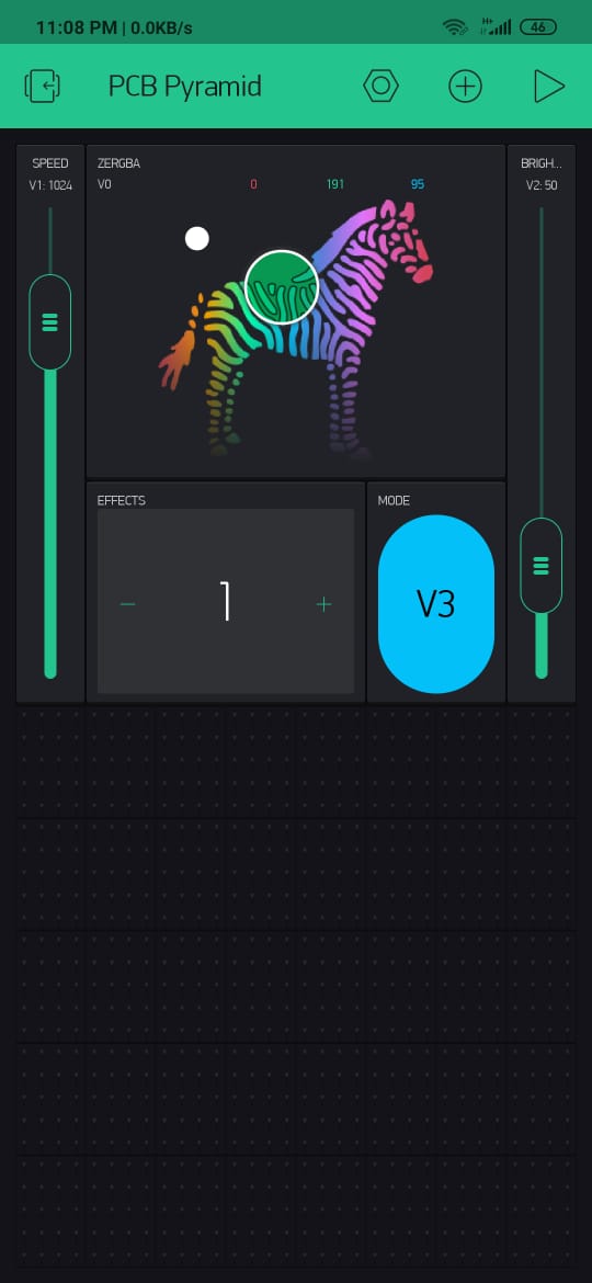
– We need a zeRBGa widget for color selection. Then we need to set the parameters. I have selected the pin to Virtual pin V0 and to output type to marged.
– Then we need two sliders for changing the Speed of the effects and the brightness of the LEDs. Set the virtual pin to V1 & V2 accordingly. Set the value from 10 to 5000 for the first slider and 0 to 255 for the second slider.
– Then I took a button and set it’s virtual pin to V3. This will be our mode changing button.
– And finally I took a numeric input widget which I will use to change the custom defined effects. I set its virtual pin to V4 and the value ranges from 1 to 9.
After that was done click the Play button on the top right corner. And power up the Pyramid.
After it is connected to the internet you can use the app to change its color and brightness as well as toggle between different effects remotely from your smartphone.
WORKING VIDEO:
See the working of LED pyramid below and subscribe to this channel to support me with my projects.
Hope this project was interesting and help you build something creative and attractive. Follow our website for more of these IOT projects. If you have any queries, feedback do leave them in the comments section below.

 I always had this crazy idea of making a 3D object using PCBs. Yes, the very same Printed Circuit Board that we use in various projects. All it takes is being good at designing PCBs and lot of creativity. In this article, I am going to take you through step instructions on making this LED pyramid. By following these steps you can make one for yourself well.
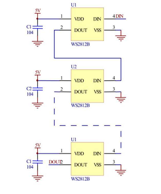

 using LED's")


