Who doesn’t love playing games with friends and family. Be it a party or get together a little fun game can make things interesting. This project demonstrates working and building a Laser tag phasor gun that can be used to play Laser tag game. This article shows only two pieces however you can build as many as you want based on the number of participants in this game. If you are not aware of this game, here is an article that could help you to get up to speed.
Many years ago, a company hired me as a consultant to develop a simple Laser Tag unit that could be put in an oval housing and attached to kids shoes. They could remove the units from their shoes and play laser tag. I developed the circuit and it worked really well. The company that hired me loved the result.
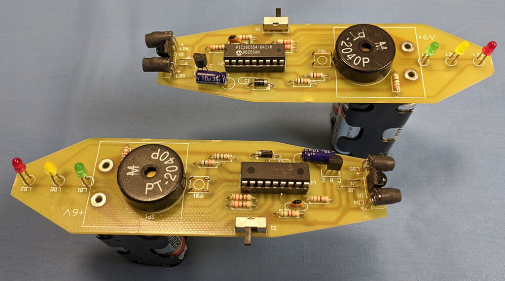
Moving on, I built the units shown in Picture 1. They work great are fun to use. My kids used to play laser tag with them a lot when they were young. Each Laser tag unit has a trigger to shoot the laser pulse and three LEDs to indicate how many time you have taken hit and buzzer to sound when taken a hit or indicate game over when taking more than 3 hits.
Picture 1: Assembled Laser tag gun
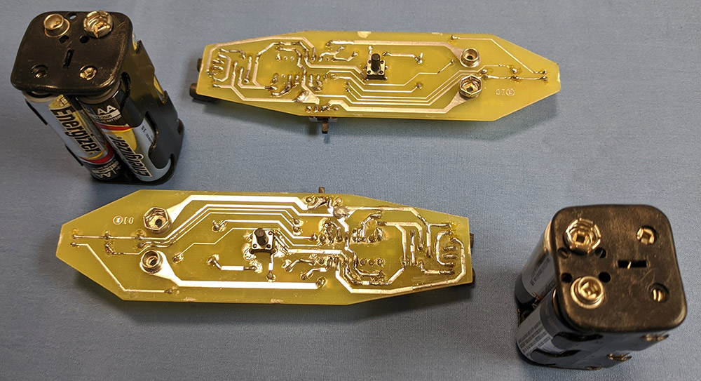
Picture 2 shows the bottom side of the PCB. The battery snap connectors and the trigger switch can be seen.
Picture 2: Bottom side of PCB showing battery terminals and trigger switch.
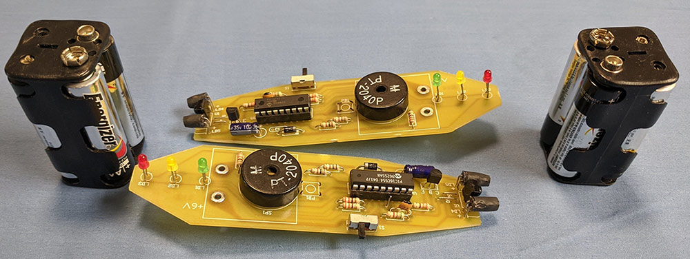
Picture 3: Laser Tag Phasors shown with their battery “handles” disconnected.
Circuit diagram of Laser gun:
Theory of Operation
Please refer to the schematic in Figure 1 for the following discussion of the circuit description and theory of operation. The laser tag phasors consists of two identical units. The schematic in Figure 1 shows just one of the laser tag phasors.
There are two IC’s that are the core of the Laser Tag Phasor, (LTP). U1 is a 40 KHz IR sensor used in many products that utilize IR remote controls. When it sees an Infra-Red pulse train at 40 KHz, its output goes low, otherwise it remains high. Micro-controller U2, a PIC16F627A, has programming that records the number of hits, flashes the proper LED’s and makes sounds related to power-up, recorded hits, and dying after four hits. The ON/OFF switch must be turned OFF and then ON to reset the unit and make it operable. Pressing S2 causes the unit to send out a burst of 256 Infra-Red pulses at an 8% duty cycle and a 40 KHz rate, via Q1, D4 and D5.
V1 consists of a battery pack that holds 4 “AA” batteries. S1 is the ON/OFF switch. Diode D6 prevents damaging the circuit if a reversed polarity voltage is connected to the circuit. Further, D6 drops the voltage to 5.4 volts to keep the circuits voltage at a safe level for U1 and U2. The Green, Yellow and Red LED’s show the number of hits, 1, 2, 3 respectively. PZ1 outputs the sounds and its output is reduced by resistor R1.
Set Up:
When building the units, put black shrink wrap tubing around the two IR LED’s to narrow the IR beam. If you wish to limit the hit angle, a small piece of tubing can be glued to the IR sensor to limit the angle of incoming IR signals. You can see the black tubes on the IR LED’s in Picture 1. Battery snaps that are riveted to the PCB were used to connect the four-cell “AA” battery pack to the unit which also serves as the handle for the laser tag phasor. This project includes Gerber files, the source code, BOM, and production hex file to program the PIC16F627A micro-controller. Have fun building and using the Laser Tag Phasors.
Figure 2: PCB board layout
Note that the circuit board layout is double sided. You should order a double sided board so that the component pads will be plated through and allow soldering from either side. You can use the service of JLCPCB to order the PCB units.
Hope this project liven up your party or get together even better. If you have any queries, suggestions or feedback do post them in the below comment box. Would love to see Photos of this Laser tag unit in action. Happy DIY 🙂
Hi Jesse, Good catch. You can use any general purpose NPN transistor like 2N4401, 2N2222. It provides higher current to drive the IR LED’s. Regards, Ron

 Theory of Operation
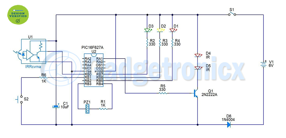
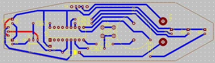


Please be aware that on the PCB layout a trace from S2 to Q1 is missing. You may resolve with an additional wire.
Dear Ron,
Thank you for the interesting project! There seems to be a missing PCB trace from the switch S2 to the anode of the diode.
Wim
Hi Jesse, Good catch. You can use any general purpose NPN transistor like 2N4401, 2N2222. It provides higher current to drive the IR LED’s. Regards, Ron
Thank you Ron,
I appreciate the reply.
You’re missing the transistor (Q1) in the BOM.