With (almost) endless combination of color and brightness, the addressable RGB LED strip is now one of the most commonly used on Arduino lighting projects. The main reason for that is the option to control not just the color and brightness, but controlling each led individually – hence the addressable. And highlighting part is that this RGB LED strip is capable of producing any color provided if you know its RGB code.
SO HOW IS THAT POSSIBLE:
Each led is built from 3 color led (same as any RGB led) that is controlled by a built-in IC. The IC has its own protocol, and can receive data from the Arduino over 1 wire. Lucky for us, there are a few really good libraries that allow us to send color commands to the led without having to know the protocol itself – how lucky are we?
In this tutorial I will be covering the FastLED library. The reason for that is that this library support many different addressable LED IC, you can see the full list here. I will be demonstrating things with what is referred to as NEOPIXEL, a term marked by adafruit for the WS2182 & SK6812 LED control IC. This are the most common LED IC out there today. Note that this type of addressable LED comes in many forms, it can be an individual led on a small PCB, sets of them on Sticks, or rings or long Strips of 30/60 LED per meter, with coating for water protection and without. But in heart they are all the same, “Adafruit neopixel” variety.
GETTING STARTED WITH RGB LED STRIP:
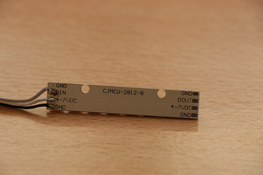
Note that the LED has 3 connector points:
1. GND – which will be connected to the ground pin on the Arduino. Remember to share grounds in case of using external power supply.
2. VCC – power supply pin, in our case we will be using the 5V from the Arduino
NOTE: the power consumption of this type of LED are about 50 milliamp when in full brightness on all colors, so if using more than 4 LED you might want to consider an external power supply not to exhaust the Arduino power regulator (limited at 200ma on uno for example).
3. DI – data in, this connector will be plugged into one of the Arduino digital pins, in our case pin 3.
In the LED strips there are direction for connection. You will notice either DI and DO, which is DATA IN and DATA OUT. The DI will be connected to the Arduino and the DO will be connected to the DI of the next LED in line.
After connecting the LED to the Arduino we will need to install the library. In order to do it, open the Arduino IDE, click on “Sketch” in the menu, then from the “Include library” sub menu, choose the “Manage libraries…”. In the search box type “fastled” there will be only one result, click on it and click on the “install” button. And we are good to go. Let’s turn on the light.
Let’s first test that we got everything in place by running the library blink example, go to “File” – “Examples” and then scroll till you see the “FastLED” sub menu and choose “blink” out of the list.
CODE:
#include "FastLED.h"

// How many leds in your strip?
#define NUM_LEDS 8

// For led chips like Neopixels, which have a data line, ground, and power, you just
// need to define DATA_PIN.  For led chipsets that are SPI based (four wires - data, clock,
// ground, and power), like the LPD8806 define both DATA_PIN and CLOCK_PIN
#define DATA_PIN 3
#define CLOCK_PIN 13

// Define the array of leds
CRGB leds[NUM_LEDS];

void setup() {
      // Uncomment/edit one of the following lines for your leds arrangement.
      // FastLED.addLeds<TM1803, DATA_PIN, RGB>(leds, NUM_LEDS);
      // FastLED.addLeds<TM1804, DATA_PIN, RGB>(leds, NUM_LEDS);
      // FastLED.addLeds<TM1809, DATA_PIN, RGB>(leds, NUM_LEDS);
      // FastLED.addLeds<WS2811, DATA_PIN, RGB>(leds, NUM_LEDS);
      // FastLED.addLeds<WS2812, DATA_PIN, RGB>(leds, NUM_LEDS);
      // FastLED.addLeds<WS2812B, DATA_PIN, RGB>(leds, NUM_LEDS);
  	  FastLED.addLeds<NEOPIXEL, DATA_PIN>(leds, NUM_LEDS);
      // FastLED.addLeds<APA104, DATA_PIN, RGB>(leds, NUM_LEDS);
      // FastLED.addLeds<UCS1903, DATA_PIN, RGB>(leds, NUM_LEDS);
      // FastLED.addLeds<UCS1903B, DATA_PIN, RGB>(leds, NUM_LEDS);
      // FastLED.addLeds<GW6205, DATA_PIN, RGB>(leds, NUM_LEDS);
      // FastLED.addLeds<GW6205_400, DATA_PIN, RGB>(leds, NUM_LEDS);

      // FastLED.addLeds<WS2801, RGB>(leds, NUM_LEDS);
      // FastLED.addLeds<SM16716, RGB>(leds, NUM_LEDS);
      // FastLED.addLeds<LPD8806, RGB>(leds, NUM_LEDS);
      // FastLED.addLeds<P9813, RGB>(leds, NUM_LEDS);
      // FastLED.addLeds<APA102, RGB>(leds, NUM_LEDS);
      // FastLED.addLeds<DOTSTAR, RGB>(leds, NUM_LEDS);

      // FastLED.addLeds<WS2801, DATA_PIN, CLOCK_PIN, RGB>(leds, NUM_LEDS);
      // FastLED.addLeds<SM16716, DATA_PIN, CLOCK_PIN, RGB>(leds, NUM_LEDS);
      // FastLED.addLeds<LPD8806, DATA_PIN, CLOCK_PIN, RGB>(leds, NUM_LEDS);
      // FastLED.addLeds<P9813, DATA_PIN, CLOCK_PIN, RGB>(leds, NUM_LEDS);
      // FastLED.addLeds<APA102, DATA_PIN, CLOCK_PIN, RGB>(leds, NUM_LEDS);
      // FastLED.addLeds<DOTSTAR, DATA_PIN, CLOCK_PIN, RGB>(leds, NUM_LEDS);
}

void loop() {
  // Turn the LED on, then pause
  leds[0] = CRGB::Red;
  FastLED.show();
  delay(500);
  // Now turn the LED off, then pause
  leds[0] = CRGB::Black;
  FastLED.show();
  delay(500);
}
EXPLANATION:
1. With this line we include the library to this sketch #include “FastLED.h”
2. This line defines the number of LED that are connected, in this sketch will only be using one LED, so you can just leave it as is. #define NUM_LEDS 1
3. The following 2 lines define the data and clock pins. In our case we only need to set the data pin, since the type of IC in the neopixel family do not have clock pin.
#define DATA_PIN 3 & //#define CLOCK_PIN 13
4. Now we create the led object array. So we can refer to it in the rest of the code. CRGB leds[NUM_LEDS];
5. In the setup section you will find a lot of commented out lines with the same format, just different Type of IC, we will be using the uncommented one – the NEOPIXEL. FastLED.addLeds<NEOPIXEL, DATA_PIN>(leds, NUM_LEDS);
6. Within the loop we do 2 operation on the led[0] which is the FIRST led in the array of LED(s) in case we have more than one connected we first set its color to “Red”
leds[0] = CRGB::Red;
7. Then we set the actual led output by calling the show() command. The reason for this 2 commands method is to allow us to make changes in more than one LED before we actually apply thus changed to the strip itself – FastLED.show();
8. After delaying for 500 milliseconds we do the same thing just this time with the color Black, which in return turn the led off. leds[0] = CRGB::Black; & FastLED.show();
9. Then we delay for another 500 milliseconds and the loop gets repeated, and we got a led that is blinking in red.
10. The list of available colors by name can be found at the top of this page.
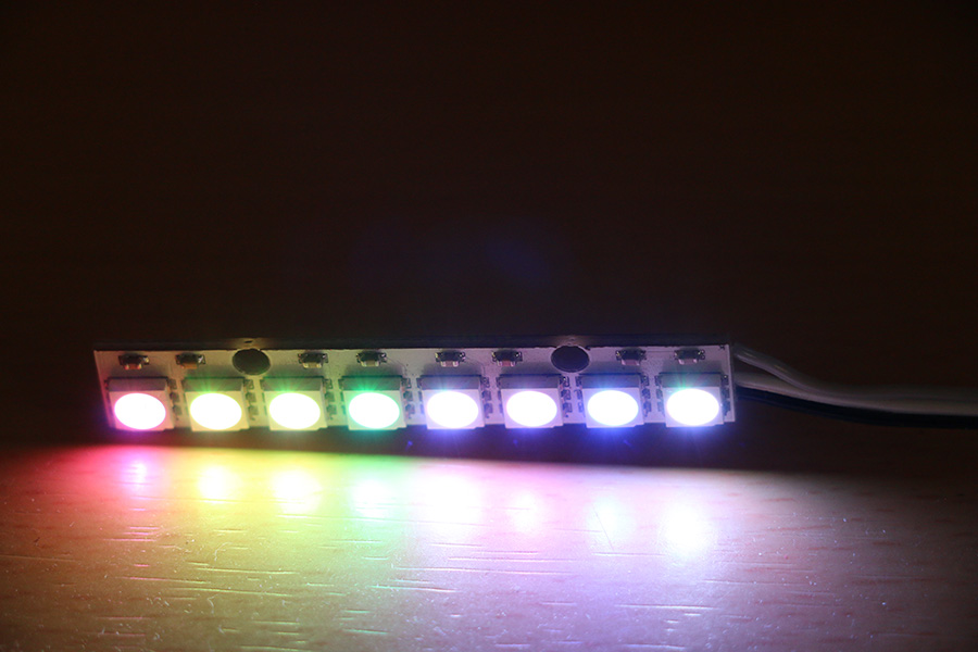
Now this was all fun and games, but we are now juts blinking one LED this is not we are here today. Now let’s control the entire strip of LED. For this example, I connected a strip of 8 LED. The following code will change the color of each led to a random color and set it to the strip every 50 milliseconds.
CODE:
// include library
#include<FastLED.h>

//define number of LED and pin
#define NUM_LEDS 8
#define DATA_PIN 3

// create the ld object array
CRGB leds[NUM_LEDS];

// define 3 byte for the random color
byte  r, g, b;

void setup() {
  // init the LED object
  FastLED.addLeds<NEOPIXEL, DATA_PIN>(leds, NUM_LEDS);
  // set random seed
  randomSeed(analogRead(0));
}


void loop() {
  // loop over the NUM_LEDS
  for (int cur = 0; cur < NUM_LEDS; cur++) {
    // chose random value for the r/g/b
    r = random(0, 255);
    g = random(0, 255);
    b = random(0, 255);

    //set the value to the led
    leds[cur] = CRGB (r, g, b);
  }
  // set the colors set into the phisical LED
  FastLED.show();

  // delay 50 millis
  FastLED.delay(50);

}
EXPLANATION:
Same as in the previous example, we include the library, set the number of LED(s) and the pin the LED(s) are connected to and initiate it in the setup. But this time we create random color, we loop over the amount of LED using the NUM_LEDS variable with in the loop. We then set random number between 0 to 255, and then using the CRGB command we set it to the led with in the array.
1. for (int cur = 0; cur < NUM_LEDS; cur++) {
// chose random value for the r/g/b
r = random(0, 255);
g = random(0, 255);
b = random(0, 255);
2. //set the value to the led – leds[cur] = CRGB (r, g, b);}
3. And the we apply it to the LED(s) by calling the show() command FastLED.show();
4. The FastLED library comes with a DELAY function as well, it’s not needed with Uno since the arduino has its own built-in function, but in case you are using a system with no delay function, this can be handy feature to have FastLED. delay(50);
5. Now this give you a nice overview of the use of addressable LED, now all you need is to think what you want to do with it?
6. This library has many very cool build-in functions for creating movement, calculating value of RGB, HUE and so on. If you want to explore it here are 2 great links :
Please note that there is a limitation to the library and its memory, since all the data has to be buffered in memory of the board, you are limited on the amount of LED you can control. For example, with the Uno, and it depends on the rest of your sketch memory use, you can run up to about 500 LED.
WATCH VIDEO DEMO BELOW:
Hope this tutorial helped you get started on RGB LED strip and I believe you will have fun playing with these. Happy making 🙂