Clock pulses are lifelines of digital circuits and there are different types of oscillators to produce the clock pulses for our circuits. But out of all nothing beats the efficiency and stability of a crystal based oscillator. Even microcontrollers use Crystal oscillators because of its stability and accuracy to produce clock pulses at predefined frequency. Next time you don’t have to worry too much when your project demands stable square wave input. Here in this circuit we will see how to use a quartz crystal to generate square waveform and working explanation of it. You can find lot of other useful circuits in our “Circuits Library”.
Quartz Crystals:
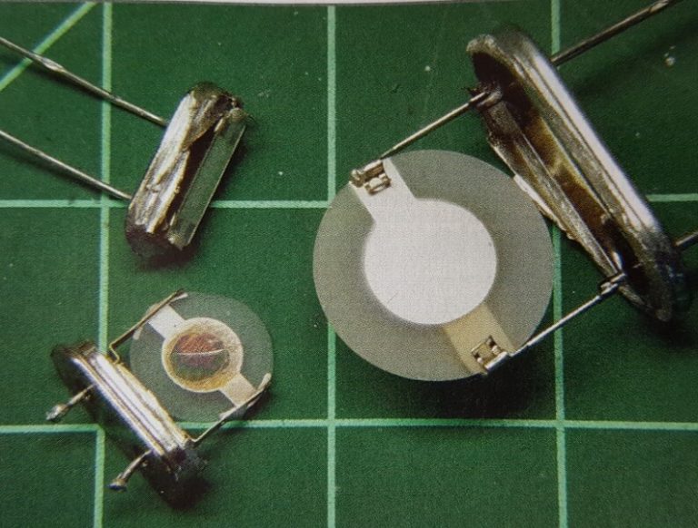
Inside a crystal ( Image courtesy: www.circuitcrush.com )
Quartz crystals works based on Piezo electric effect which is when a electric charge applied to quartz crystal plates, it vibrates. Basically converting electric energy to mechanical energy. This property is used to build quartz crystals where Quartz sheets are placed with electrodes connected to it. When electric charge / current is applied, it produces vibration in predefined frequency which in turn can be derived as steady waveform using external components connected to it. This is what we are exactly going to do in this circuit, use external components with it to get desired signal of fixed frequency.
Working of Crystal oscillator circuit:
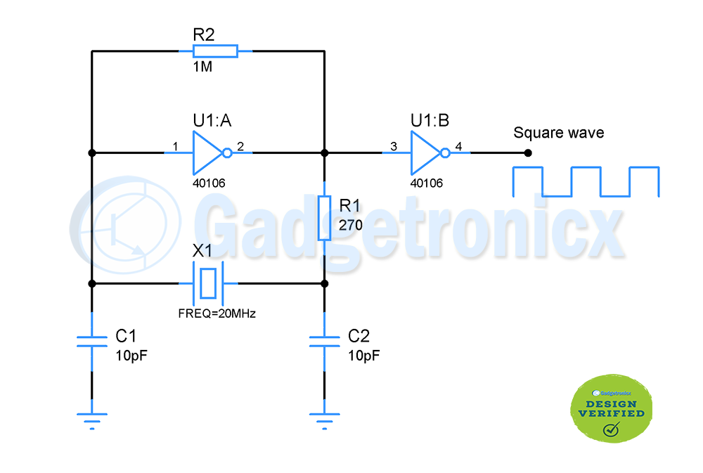
Inverter U1 triggers the start of this oscillator circuit. With the feedback resistor R1 connecting from output to input, it feeds portion of output to input. Consider inverter is at low state when it is initially ON. The output of inverter goes to high state, this is fed back to input. This charges up the capacitor C1 and the inverter toggles its output back to low state. By doing this Inverter will be operated in it’s linear region. The maximum output voltage from U1 will be Vcc/2 in this circuit. This R1 and U1 combination will generate a sine wave that is 180 out of phase.
On the other hand the Resistor R2 limits the current flowing into the crystal to prevent damage. The sine wave from U1 in combination with Capacitor C1, C2 and crystal will generate another sine wave. This will 180 out of phase as well. These two 180 out of phase signals together will be give signal output which is 360 out of phase which will satisfy the Barkhausen criteria for stable and sustained oscillation.
U2 acts just as a inverter taking the sine wave input and gives square waveform as output of 20Mhz frequency. The component selection of R2, C1 and C2 is quite important to attain the desired frequency. C1 and C2 should be 10pF and R2 should be 270 ohm to get stable 20Mhz square wave. You can check what load capacitance you should use with your crystal in the datasheet to operate in your desired frequency.
Hope getting a stable square for your projects will not be a problem anymore. Check out other electronic circuits in our website. If you have any queries or feedback, do post them in the comments section below and we will help you out.