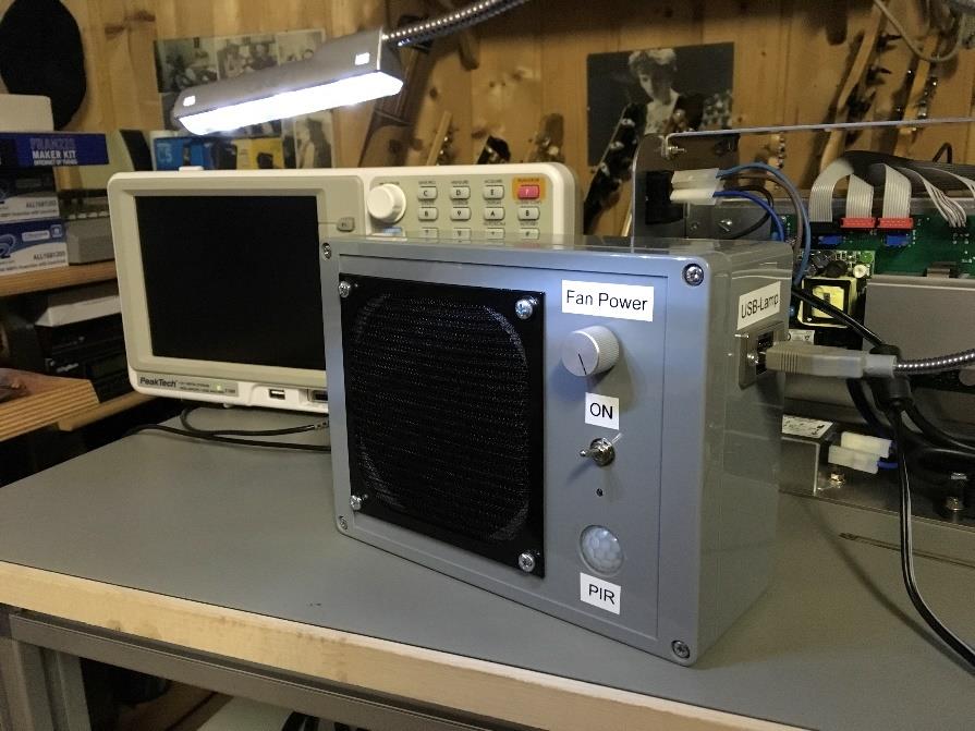
I have been soldering for four decades now without a solder fume extractor. In production, it is a must. So, why not use one at home ? Solder fumes stink and are probably not a very healthy thing to inhale.
PROBLEM:
Last year, I have seen a solder fume extractor with a PIR sensor (Passive InfraRed sensor), that is a motion detector, which is widely used in burglar alarm systems and it became quite cheap while the past years. Also there are modules available on eBay and many online maker stores. They will detect the movements of warm objects, like your body, hands or the soldering iron. But the problem with the PIR sensors is, that they need some time (60 secs) to calibrate after being powered up. While that time, they are not working properly.
FEATURES OF THIS SOLDER FUME EXTRACTOR:
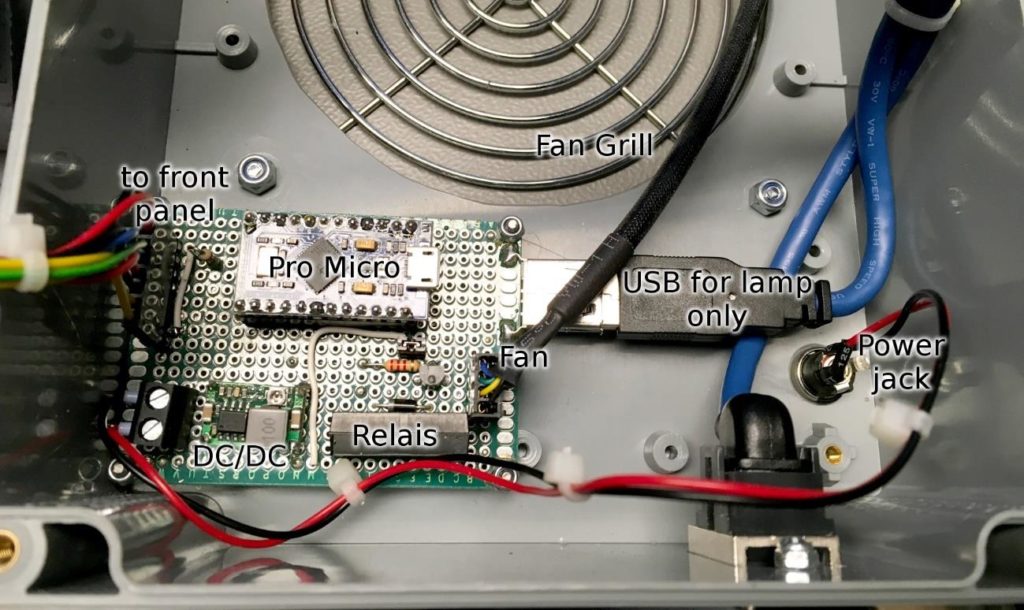
To rectify the above problem I have decided to use a microcontroller (the Pro Micro is pretty cheap and can be used like an Arduino Leonardo). This way, I can switch on the fan after powering the solder fume extractor. Nobody really wants to wait a minute before soldering, I think. At least not me.
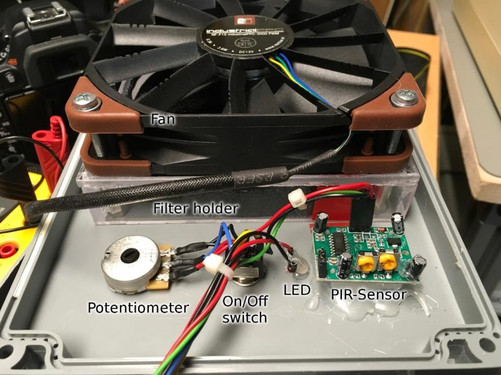
I also had a fan, which is PWM controlled and I was curious about using that feature. So, this is, why I have a potentiometer to control the fan power. This is not a really important feature. If you have a fan, which does not have PWM control (a four-pin connector), just leave it out (you do not need the potentiometer, either).
There is a USB lamp in my design. And I had one in my drawer for a couple of years. It is a nice thing, if you bring your notebook to a dark place, but I have never done that. I thought, utilizing this lamp in my solder fume extractor might be cool. And yes, I like it. The disadvantage is the high current consumption, which requires a different way to generate the 5V for the Arduino, the PIR sensor and also the USB-lamp. This is the reason, why I am using a DC/DC-converter to generate 5V from my 12V power supply. If you do not want that lamp, use a 7805 linear voltage regulator. And this will definitely be sufficient to power the pro micro.
So, now we should talk about the guts of the device. The fan is sucking the air and solder fumes through some activated carbon mats. And I have ordered mine from ebay. They are held in a frame, which is made from acrylic glass. Also Ply wood would a sufficient material, too. Or in case you have a 3D printer you can make your own encasing. The potentiometer is a voltage divider, so anything between 1k and 100k should work here. I think mine is a 10k Pot. I have used the hot glue to fix the PIR sensor.
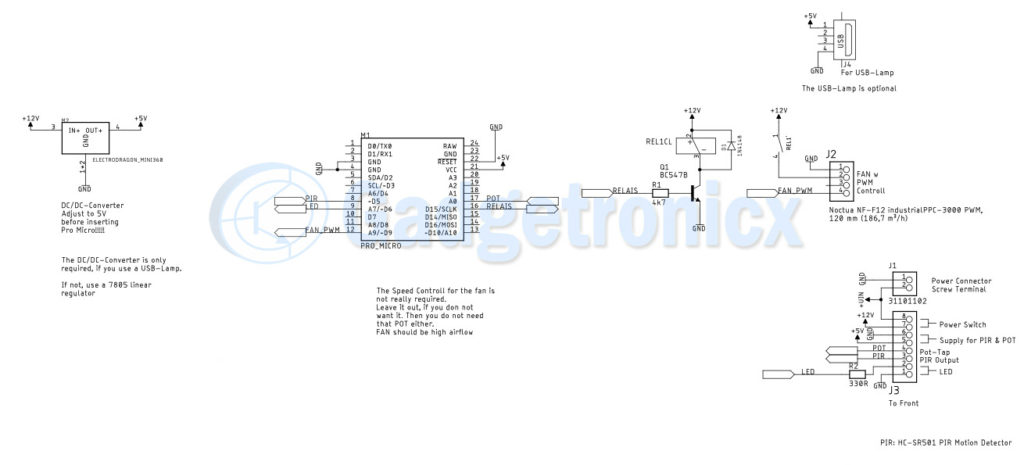
SCHEMATIC DIAGRAM:
Click to enlarge view
THE SOFTWARE:
The software is an Arduino sketch. You can download the Arduino IDE from Arduino.cc. All you need to do is to compile and upload it to the Pro Mini (select the Arduino Leonardo board for that). An ordinary USB-Micro cable is required for uploading.
You need to download and install the TimerOne.h library. Google will find the download for you. Timer1.initialize( 1000 ) means, that timer1 is initialized to 1000µsecs. If you want a higher PWM frequency, because you can hear the 1kHz from your fan, you can set a shorter cycle time, like 50msecs. For me, it was not required, so I did not try it yet.
#include <TimerOne.h>

const int rel = 15; const int pir = 5; const int led = 6; const int pot = A0; const int fanpwm = 9;

int avalue;
int value;
int countdown = 0;
int pirStatus; int st_on = 0; int led_on = 0;
int bl_count = 0;

void setup() {
// put your setup code here, to run once:
pinMode( rel, OUTPUT ); // Relais Pin
pinMode( pir, INPUT );  // PIR/Bewegungssensor Input pinMode( led, OUTPUT ); // LED output
pinMode( fanpwm, OUTPUT ); // Fan PWM output
Serial.begin( 9600 );
printf( "Dunstabzug v0.00\n" );
Timer1.initialize( 1000 );  // Timer 1 is 1000Hz digitalWrite( rel, HIGH );  // Relais on digitalWrite( led, HIGH );  // led On
Timer1.pwm( fanpwm, 1023 ); // Full power
delay( 1000 );              // Wait a second
countdown = cntdwn_ini;     // initialize a long on phase to allow PIR
to settle
}

void loop() {
pirStatus = digitalRead( pir );     // read PIR
if (pirStatus == HIGH) {            // is active?
if (countdown < cntdwn_def) {     // only set countdown, when is it less than cntdwn_def to allow the long on phase in the beginning
countdown = cntdwn_def;
}
digitalWrite( led, HIGH );         // switch on LED to indicate PIR
motion detected
}
else if (st_on == 1) {               // else if fan is running digitalWrite( led, LOW );          // switch of LED (to let the LED
blink, when fan is not running)
}


if (countdown > 0){                  // count down not elapsed?
avalue = analogRead( pot );      // read potetiometer
value = map( avalue, 0, 1023, 500, 1023 ); // calculate fan pwm
Timer1.pwm( fanpwm, value );     // set fan pwm digitalWrite( rel, HIGH );       // switch on relais countdown--;                     // count down
st_on = 1;                       // status is on
}
else {                               // count down elapsed Timer1.pwm( fanpwm, 0 );         // switch off fan pwm st_on = 0;                       // status is off digitalWrite( rel, LOW );        // switch off relais
if (bl_count > 0) {              // blinking periode is blcnt_def bl_count--;                    // if > 0 count down
}
else {
bl_count = blcnt_def;          // else restart the blinking
periode
}
if (bl_count < blon) {           // should the led be on?
digitalWrite( led, HIGH );     // yes: switch led on
}
else {
digitalWrite( led, LOW );      // no: switch led off
}
}
delay( 100 );                        // cycle time of the main loop:
approx 100ms
}
You can download the .ino and Eagle schematic files .sch files for this project below.

 The potentiometer is a voltage divider, so anything between 1k and 100k should work here. I think mine is a 10k Pot. I have used the hot glue to fix the PIR sensor.