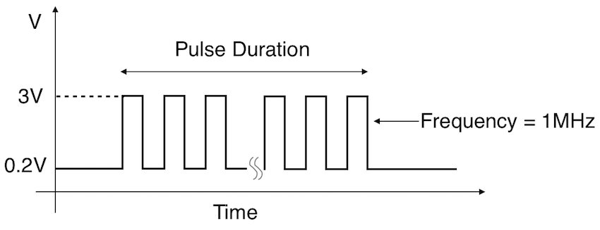
Let’s start by understanding what is pulse? This is one of the most concept in basic electronics. In digital systems there are two possible output states digital high or “1” and digital low or “0”. Pulse is a continuous signal which contains sequence of these 1’s and 0’s in it. The below image shows a digital pulse that has logic 1 or high logic at 3V and logic 0 or low logic at 0.2V. This alternative logic states repeats throughout the time period thus making it a digital pulse signal.
What is PWM or Pulse Width Modulation:
The term modulation means modulating or manipulating a signal using another signal in order to derive a signal which possess higher strength. This is quite common in transmission systems to enable transmission of the audio signal.
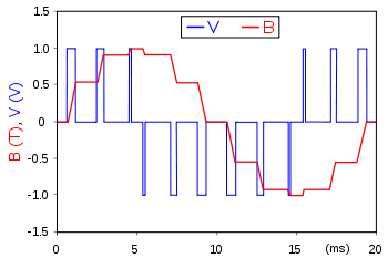
Likewise when we say PWM it means modulating the pulse of a digital signal using another signal, most commonly an analog signal.
The resultant signal of this modulation will have modified width in it’s logic states as shown in the above image. If you observe the above image closely you can see the width of high state varies from each other logic 1. This essentially means the amount of time each logic high lasts differs thus a modified width pulse signal is seen above.
Why use PWM:
PWM signal has significant role in power PCBs, driver circuits and so on. When a device is driven using a PWM signal rather than a steady DC signal. Due to the varying nature of the ON and OFF state, using PWM we will be able to control the amount of time current actually flows through the device.
When the pulse is in ON state current will be delivered to the device, when signal is in OFF state current will no flow through. When frequency of the pulse is high enough the device will not see any interruption in its power supply at all thereby operates normally while consuming less current. This is further explained below.
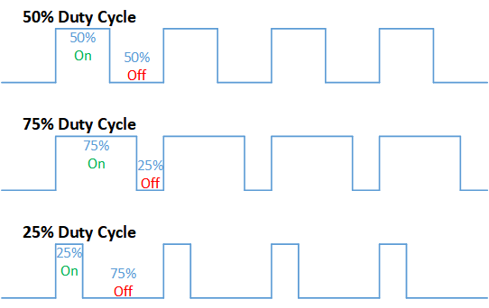
The duty cycle is defined as the percentage of time high state is exhibited in per cycle. Using duty cycle we can deduce Average current from a PWM signal the output can be obtained by taking an average of ON time and OFF time.
Consider a device is driven by a PWM signal of duty cycle 50% duty cycle that is timing for high state and low state is equal. Now we can say that the current consumed by the device will be 1/2 the current consumed when driven by a DC signal/
Similarly 25% duty cycle PWM signal gives 1/4 and 75% duty cycle PWM gives 3/4 current to the device than a plain DC signal.
Advantages of PWM
PWM signals will save power by providing average current to the target device.
Efficient way to control the speed of motors and brightness of LEDs.

 What is PWM or Pulse Width Modulation: