Summers are at its peak now and I thought to myself now might be the time to install a fan close to my work space. However to do it power efficient, Switch operated fan is not a great idea. So I thought to design a Motion sensor Fan circuit that can sense my motion and turn the Fan on or Off based on my presence in the workspace.
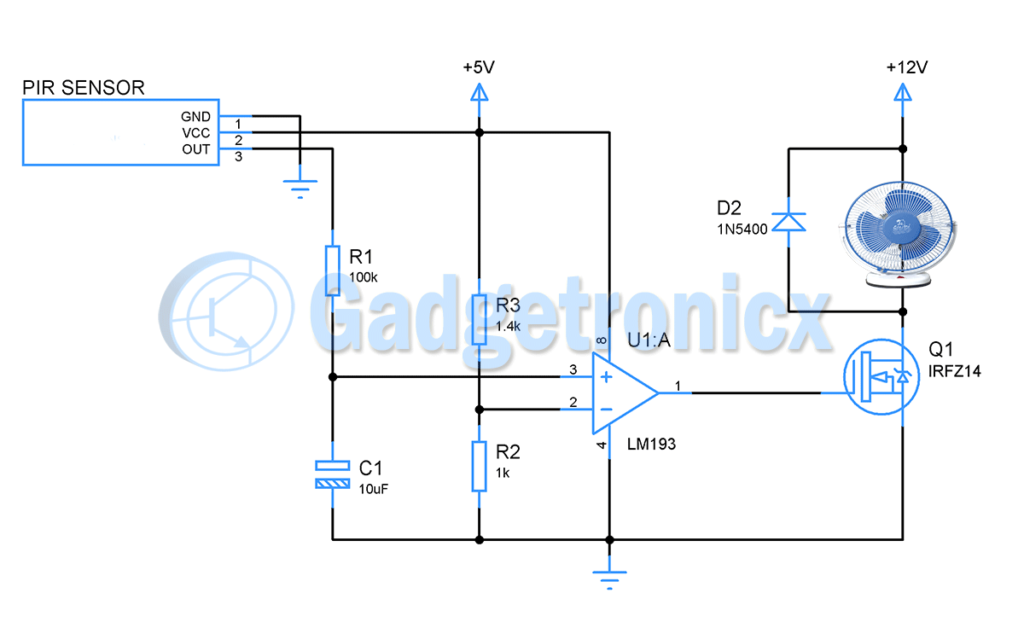
CIRCUIT DIAGRAM OF MOTION SENSOR FAN:
Motion Sensor Fan
The working of this Motion detector fan circuit starts with a PIR motion sensor. PIR ( Passive Infrared Sensor ) is widely used to detect movement or motion. This sensor emits the IR beam and measures the IR radiation radiated from the objects located within a distance. By this way it detects any movement within a certain proximity. When there is no movement in front of the sensor it’s output will be in low state. Whereas if there is any movement the output instantly switch to high state which is 3.3v.
We must know that Sensors are not perfect there might be some false triggering even before we approach the work space. Or there might be instances while working I have to move a bit from my work space. We don’t want the Fan to turn ON nor OFF in these cases. So we are going to use a RC timing circuit to generate a time delay after PIR sensor detects movement to make sure its not a false trigger.
RC NETWORK:
When motion is detected by PIR sensor, it’s output voltage will be equal to 3.3v. Now the Capacitor C1 starts to charge via Resistor R1. Calculating the Time period generated by R1C1 value
When you observe a Capacitor charging curve, for a time period of 1T or 1RC capacitor will only charge up to 63% of applied voltage. So in this case 63% of 3.3v will be 2.1v. Now this should be considered as reference voltage for comparator in order for us to activate the motor one second after PIR sensed motion. Using the voltage divider R3 and R2 ( 1.4k and 1k ) we feed the fixed reference voltage of 2.1v to comparator’s inverting input. When capacitor voltage crosses this 2.1v mark the comparator gives high output.
MOSFET DRIVER:
When the comparator output turns high, it will activate the MOSFET IRFZ14 and likewise the DC fan. Output current from LM193 is pretty low to activate a DC fan. So adding a driving stage using MOSFET or Darlington transistors is mandatory. This DC fan rated 12v/ 1A is connected to drain pin of MOSFET. When output from comparator goes high, current starts flowing from drain to source thus turning the Fan ON.
TURN OFF:
This Smart Fan will stay ON as long as PIR sensor sense user presence. Once the user away moves from the workspace, output of PIR will switch back to low state and this will trigger discharging of capacitor. When voltage in capacitor drops below 2.1v the comparator switches its output back to low state turning the DC fan OFF.
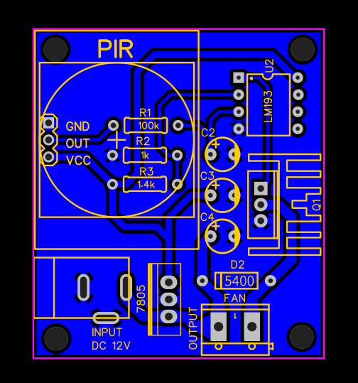
PCB DESIGN:
Here is the PCB design for this Motion sensor fan circuit, This circuit should be powered using DC adapter and the fan you wish to control should be connected to the “Fan terminals”. You can download Gerber for the above design below.


My application is HDPE pipe moment speed to be measure sir
I wish to make product speed measuring circuit with relay .
Can you explain your circuit need with little bit of detail ?