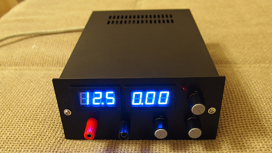
Every lab needs to be equipped with essential equipment. Out of all I would say power supply is most important since it powers up the projects. Batteries, DC adapters can do fine job but as demand grows and project gets bigger a professional and adjustable power supply becomes a necessity. To cater that I have designed an adjustable 50V / 5A power supply with a variable output from 0V to 50V and adjustable current limiting from 0A to 5A. Most simple power supplies cant get the output to come down to exactly 0V or 0A. But in this circuit, the differential amplifiers have a negative power supply rail at (-3V), which can pull the output down to exactly zero.
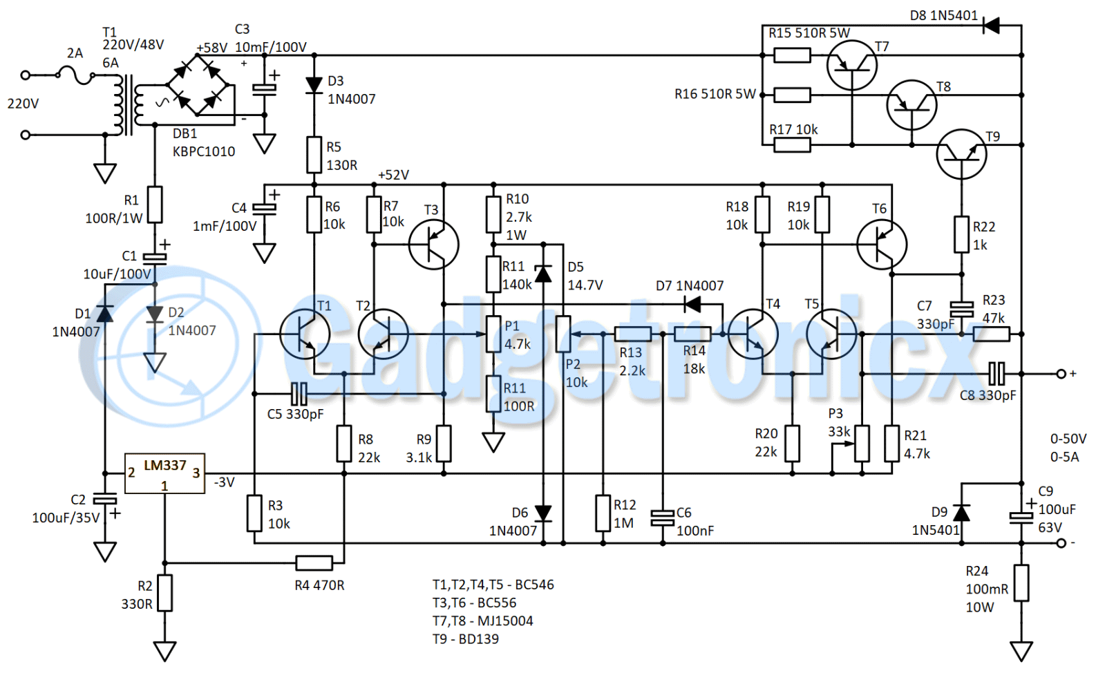
CIRCUIT DIAGRAM OF BENCH POWER SUPPLY:
WORKING:
The power supply relies upon two differential amplifiers made out of Transistors T1 to T6. The first one being responsible for controlling the output current limiting. The second differential amplifier controls the output voltage. They both are driven by the reference voltage created by D5 and D6. The use of zener and a normal diode is to compensate for thermal drift of reference voltage generator. This is because they both have opposing thermal coefficients.
VOLTAGE CONTROL CIRCUITRY:
The voltage control circuitry is created from Transistors T4,T5 and T6. This works by measuring the differential voltage on base terminals of T4 and T5. One terminal is supplied with reference voltage, and the other terminal with some of the output voltage. The reference voltage created by diodes D5 and D6 is around 15.4V. Hence the differential amplifier must amplify the voltage difference by 3.4 times to match the 50V output. This is done by the voltage divider (R23,P3) connected to the inverting terminal of this differential amplifier, setting the gain to 3.4 times of input signal.
When tweaking the power supply, you must set potentiometer P2 to its upper most level. Then fine tune the maximum output voltage to 50V by P3. Since the current sensing resistor (R24) is in a low side configuration, the differential amplifier must correct for the voltage drop it makes when power supply is loaded. This is why the reference voltage generator is connected to the (-) terminal of the power supply and not ground terminal. By connecting the reference voltage generator in such a way, it allows it to drift up or down by the same amount of voltage the current sensing resistor creates as a voltage drop. Therefore it keeps the output steady through the load.
CURRENT LIMITING CIRCUITRY:
The current limiting circuitry is comprised of Transistors T1,T2 and T3. This works by measuring the voltage drop created by current sensing resistor and comparing it to a given reference voltage created by R11 and P1. I actually suggest replacing R11 with a 220k trimmer and fine tuning the maximum current limit to match your requirements.
As it is, the protection is set to enable at 5.3A. With an adjustable value for R11, you can set the protection at any level up to maybe 6-7A without compensating the circuit for increase in power. When the protection is ON, T3 drops the voltage at its collector, thus creating an appropriate potential difference through the diode D7. At this point it starts stealing some of the biasing voltage of T4. By dropping the base voltage of T4, output voltage drops sufficiently to keep the current through the load constant.
GERBER FILES:
A big thanks to Morne Stander for designing PCB for this circuit and sharing it with the community. You can download the Gerber files below
Hi, I am building this power suppply, but i have a problem, when I try to lower the voltage with P3 below 6V the voltage suddenly starts to drop, so I can’t set like 5V or 3V because it falls to 0. I really want to finish this project so i would really appreciate your help. Thanks!
Hi, surely the 220v supply should not be connected to the 0V output rail of the power supply? This would make the output line potentially lethal if the L and N input lines are incorrectly polarised. Perhaps the schematic should show the 0V line connected to protective earth (ground)? Regards, Joe
Hi Joe, Ya, that doesn’t make sense. That would defeat the purpose of having an isolation transformer. I myself might use a ct secondary and make it ground. I have a bunch of transformers I need to go through. My one bench supply just started acting up so I figured I would just build one that I can service easily. Doesn’t seem like anyone replys in this post. Did you end up building this? Regards, Ken
Hai i was planning to build my own bench power supply and i came across this circuit.
It looks good and i am planning to build this one. I would like to know the output ripple when there is a load connected as i dont have an oscilloscope of my own. If some one has measured it please let me know.
And is it ok to use a 47k pot instead of 33k?
This might sound like a dump question, but still can some one tell what displays should i use and where should i connect them.( Sorry i am new to electronics )
Hi, I was interested in your interesting project and if you provide a design for a printed circuit board, I would be interested. In that case, please send it to me at alt.ja-46it7vg(at)yopmail.com. Thank you in advance.
Hi Frank, I think someone else asked this also. Where would the voltage and current meters go in the circuit? I figured the voltage could go on the output. But not too sure about the current meter. the schematic doesn’t show any connections.
Build it and it works! after moving P3 to ground suggested by Bernard and Jean in the comments below.
Also switched the zener to 10V because I have 30V supply, don’t now if this is wright.
Had some magic smoke by accidentally reversing polarity but it only blew the two protection diodes!
Gonna try some more tweaks keep you posted


Great project!
Hi, I am building this power suppply, but i have a problem, when I try to lower the voltage with P3 below 6V the voltage suddenly starts to drop, so I can’t set like 5V or 3V because it falls to 0. I really want to finish this project so i would really appreciate your help. Thanks!
There are three errors in this circuit.
The values of resistors R15 and R16 are incorrect!
Hi, surely the 220v supply should not be connected to the 0V output rail of the power supply? This would make the output line potentially lethal if the L and N input lines are incorrectly polarised. Perhaps the schematic should show the 0V line connected to protective earth (ground)? Regards, Joe
Hi Joe, Ya, that doesn’t make sense. That would defeat the purpose of having an isolation transformer. I myself might use a ct secondary and make it ground. I have a bunch of transformers I need to go through. My one bench supply just started acting up so I figured I would just build one that I can service easily. Doesn’t seem like anyone replys in this post. Did you end up building this? Regards, Ken
Hi Very Interested in this circuit as a replacement for Mc1466L power supply I built years ago.
Can you tell me, what is the lowest regulated current limit the circuit can do, I would love to get down to say 1ma. and up to 3A 0-50V
Best Regards
Phil
Hai i was planning to build my own bench power supply and i came across this circuit.
It looks good and i am planning to build this one. I would like to know the output ripple when there is a load connected as i dont have an oscilloscope of my own. If some one has measured it please let me know.
And is it ok to use a 47k pot instead of 33k?
This might sound like a dump question, but still can some one tell what displays should i use and where should i connect them.( Sorry i am new to electronics )
By the way, “Vladislav Damyanov” thanks for sharing this project.
Hi, I was interested in your interesting project and if you provide a design for a printed circuit board, I would be interested. In that case, please send it to me at alt.ja-46it7vg(at)yopmail.com. Thank you in advance.
Hey Vodicka,
The Gerber files are now uploaded in the article. Thanks to Morne stander 🙂
Hi Frank, I think someone else asked this also. Where would the voltage and current meters go in the circuit? I figured the voltage could go on the output. But not too sure about the current meter. the schematic doesn’t show any connections.
thanks, ken
Build it and it works! after moving P3 to ground suggested by Bernard and Jean in the comments below.
Also switched the zener to 10V because I have 30V supply, don’t now if this is wright.
Had some magic smoke by accidentally reversing polarity but it only blew the two protection diodes!
Gonna try some more tweaks keep you posted
Does it really deliver the 5A at 50v? and, does the current limiter works?
dir sir…
P1, p2, p3 what this component sir?…. and un-identify conponent sir what is this… one more sir resister R11 double place… i ada symbol to r16…
i have already design pcb using altium design… thank sir for your schematic diagram…
can anyone send details of pcb for this 50v 5a power supply or where i can get it please thanks leejohnwick4@gmail.com
Hi I am new to this field. I got 220v 50-60hz to 24-0-24v 3Amp, using this circuit can I get 0-50v 0-2Amp?
Yes friend you can get 50V 2A