Power supplies are critical for most of the products/gadgets. If we didn’t consider the power supply part while designing our circuit, it can sometimes lead to catastrophic failure and we don’t want that. This is especially true when you are designing a product. There is a possibility user can ruin the product by using supply that has high voltage output than your product’s rated voltage. In such cases you need to use a overvoltage protection unit with your circuit to prevent it from failure. This is an overvoltage protection circuit that uses SCR and zener diode.
Components required
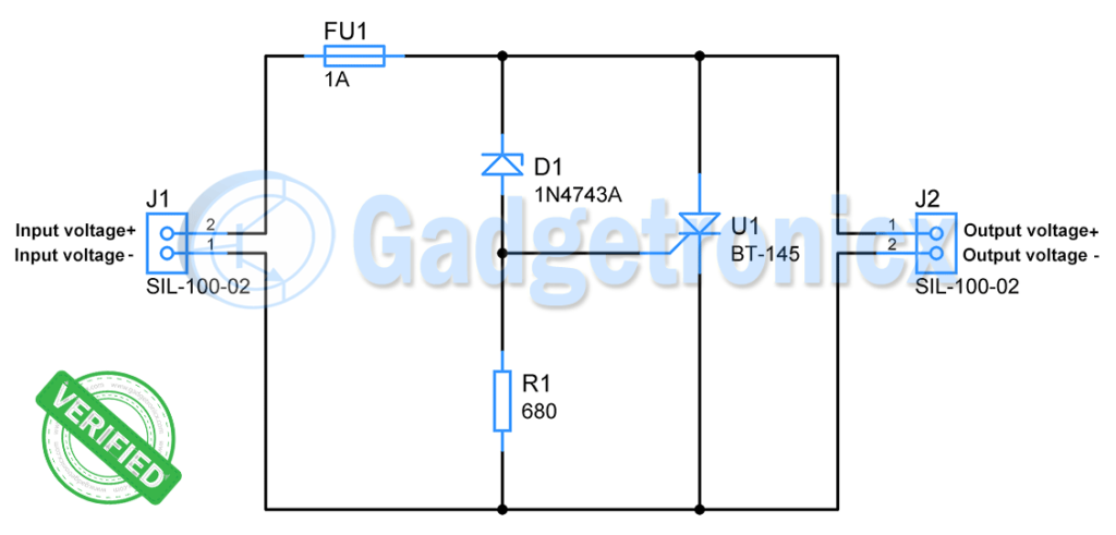
SCR ( BT-145-800R )
Zener diode(1N4743A)
Fuse(1A)
Resistor(680Ω)
Silicon controlled rectifier ( SCR ):
It is a three terminal device with terminals named as Anode, Cathode and Gate. It works like a typical PN junction diode when reverse biased. But in forward biased state current flow through Anode is determined by gate current. When a specified current ( unique for each SCR ) flows through gate then SCR acts like a regular PN junction diode. At this instant current flows through the SCR from Anode to Cathode. This also leads to a voltage drop across Anode and Cathode owing to SCR’s forward voltage which typically falls around 1V.
Zener diode:
Unlike regular PN junction diodes, it allows current to flow backwards when a certain reverse voltage is applied across it. It is known as Zener voltage. In addition to allowing current to flow through in reverse bias direction zeners hold the zener voltage across its terminals. In order to do this, it need to be supplied with a fixed current known as Zener current. Care must be taken since zener current should not exceed its limit or it will destroy the device.
Working of Overvoltage protection circuit:
The above circuit is designed to protect the circuit that connects to it from voltage over 13V. It is meant to use with 12V rated circuits / devices. Generally 12V devices will have a tolerance up to 13V. So it will establish protection over 13V and moreover this will give the power supply necessary wiggle room to operate.
In this circuit J1 is used to connect power supply and J2 to connect the device / circuit that needs to be powered and protected.
When the voltage from supply is within the 13V, zener will be not conduct current and SCR will be non conducting state. Here we are using Zener diode of zener voltage(13V) so when the power supply voltage exceeds 13V the zener diode starts conducting and current flows through it.
As stated earlier zener diode should be current limited zener current. According to datasheet the typical zener current for 1N4743A is 19mA. Using Ohms law we can calculate the resistor to use with this.
Vz = 13v
Iz = 19mA
R = Vz / Iz
=680Ω
Therefore we have fixed R1 as 680Ω.
This Zener current and voltage developed across resistor triggers the gate terminal of SCR. According to datasheet required gate current to turn ON SCR ( BT-145-800R) is 5mA. Therefore the zener current triggers the SCR and force it to conduct current.
When SCR turns ON it acts like a short circuit and therefore huge current flows from Anode to Cathode. As mentioned earlier voltage across it drops and therefore there will be no voltage exhibited at the output. This results in protecting the circuit / device that connects in terminal J2.
This huge current flow continues till the voltage from source or J1 drops below 13V. Another protection feature of this circuit is the Fuse, when current from power supply exceeds 1A, fuse will break its contact. This stops further current flow.
The fuse is quite important since many power supplies lack internal current limiting or short circuit prevention feature within itself. The fuse current rating should be lesser than the short circuit current of the power supply user may use to power this circuit. This will ensure successful elimination of current path current from power supply reaches its maximum short circuit current threshold.
Note:
Substitute the zener diode of zener voltage with your intended protection voltage
The input voltage should not exceed absolute maximum ratings of Zener and SCR.
Hope this circuit was useful to you. Check out more circuits in our Circuits library. If you have any questions or feedback leave them in the comments section below.


Very informative article, thank you