
Synthesizer circuits are the ones which is capable of producing audio signals using electronics. Modern synthesizers are quite popular now a days as it provides a ease of producing quality music. You might have seen some similar synthesizer circuits like Electronic piano, MIDI generator and so on. This circuit can add to the long list of Audio synthesizers. It can generate sound of music notes with press of buttons. In a sense this is an Electronic piano circuit.
IC MAX038:
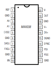
This chip is a high frequency waveform generator. It should be powered with +5V and -5V via its V+ and V- pins. You can use this +5V and -5V power supply circuit for this purpose. This chip is capable of producing three different types of wave forms: Square, Triangle and Sine.
The output frequency range of this chip is from 0.1Hz to 20MHz. Above this the output wave will be distorted in nature. The output waveform by this chip will selected by feeding appropriate logic input to A0 and A1 pins.
The output frequency from this chip depends on two factors. One is external capacitor which connects to COSC pin. Another one is the current into its IIN pin.
It also provides provisions for modifying Duty cycle and fine tune the frequency of output wave by applying voltage from -2.4V to +2.4V to its FADJ and DADJ pins. When DADJ pins are pulled to 0V the duty cycle of the waveform stays at 50%.
Similarly when FADJ and DADJ pin is pulled to 0V, frequency tuning and duty cycle adjustment feature will be turned off. In this instant the output frequency solely depends on the IIN current and Capacitance in COSC pins. Read more about this chip in its datasheet.
WORKING OF AUDIO SYNTHESIZER CIRCUIT:
MAX038 from maxim integrated is the heart of this circuit. This waveform generator is configured using external resistors and capacitors to generate signal in three different waveforms : Sine, Triangle and Square. As mentioned earlier output frequency from this chip depends on current to IIN pin and Capacitor value connected to COSC pin.
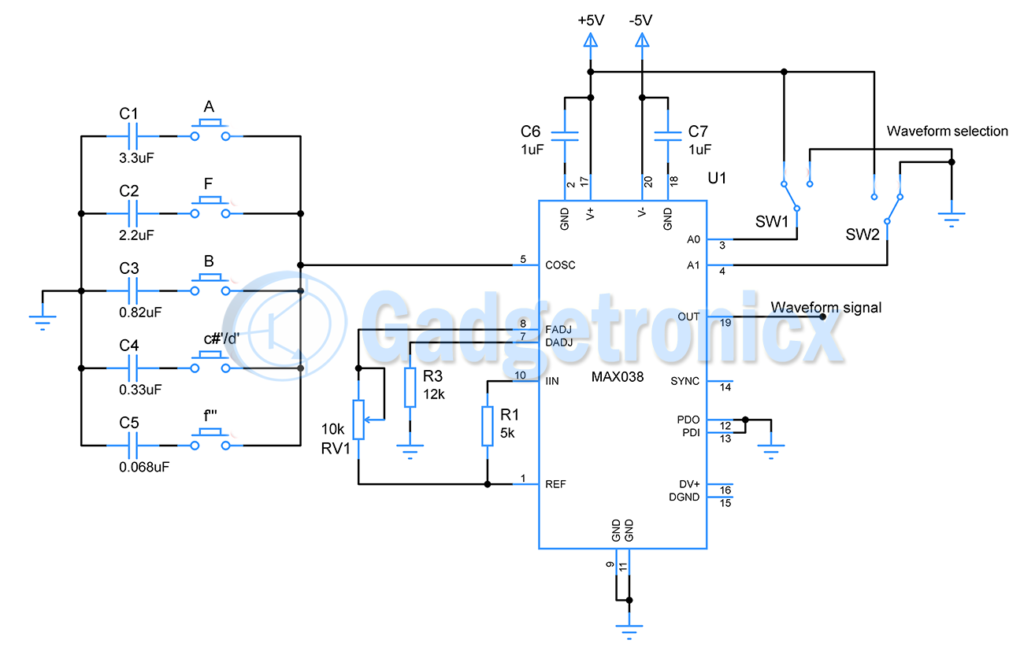
As per the datasheet the REF pin supplies a reference voltage of about 2.5V and capable of sourcing current of about 200mA. Hence we use a resistor R1 of 5k to limit the current to 100uA and feed it to IIN pin. This is because of the recommended current input to IIN pin stands from 1uA to 750uA and we choose 100uA here.
The current to IIN pin feeds the oscillator current generator, this in turn feeds the internal oscillator. External capacitor C1, C2, C3, C4, C5 connects to internal oscillator via push buttons.
The oscillator charges and discharges the capacitor when button is pressed. As a result this affects the frequency of output signal. Hence when a push button is pressed it connects the capacitor to COSC pin and therefore produces the corresponding frequency output in 19th pin.
This is governed by the formula.
Fo(MHz) = IIN( uF ) / CF ( pF )
Also a variable resistor RV2 is used here to modify the input voltage to FADJ pin. This can modify the nominal output frequency fixed using the above formula by +70% to -70%. A resistor R3 of 12k connects from DADJ to ground since we don’t need to adjust duty cycle in our circuit. Use a variable resistor instead of 12k from REF to enable this feature.
PIANO KEY FREQUENCIES:
For the purpose of fixing output frequencies for each keys of our audio synthesizer am going to use Piano key frequencies
| Notes | Frequency |
| A | 27.500 |
| F | 43.6533 |
| B | 123.4708 |
| c♯′/d♭′ | 277.1826 |
| f′′′ | 1396.913 |
I have picked piano notes and its respective frequencies for fixing the capacitance. Please note that this circuit cannot produce the sound of a piano, since piano output waveforms are quite complex and rather used its frequencies as a reference. This answer by Cedron in stackexchange offers a good explanation.
FIXING CAPACITANCE VALUES:
Let’s fix the capacitance values for above listed frequencies using the formula. Do note that you have to convert the frequency and current values to the unit specified below.
For a nominal frequency of 27.500 ( Note A ) capacitor should be
CF ( pF ) = IIN (uA) / Fo ( MHz)
= 100 / 0.0000275
CF (pF) = 3.636 x 10⁻¹² ( Capacitance is in Pico farad )
= 3.6uF ~ 3.3uF
Likewise here is the list of other Capacitance values
- Note F – 2.2uF
- B – 0.82uF
- c♯′/d♭′ – 0.33uF
- f”’ – 0.068uF
WAVEFORM SELECTION:
Output waveform can be selected by feeding appropriate logic to pins A0 and A1. Two SPDT switches ( SW1 and SW2 ) in the circuit connects to +VCC and GND alternatively. This will help us to make this selection. The below table shows the selection conditions for square, sine and triangle wave.
| A0 | A1 | Waveform |
| X | 1 | Sine wave |
| 0 | 0 | Square wave |
| 1 | 0 | Triangle wave |
Now the configuration of our MAX038 is complete. When pressing a push button, selected waveform using SW1 and SW2 of frequency fixed using capacitor connected to push button will be produced as output from this audio synthesizer circuit.
The output waveform goes from +5V rail to -5V rail with a maximum current of 20mA. This current is not sufficient to drive a speaker, therefore we need an amplifier stage to do this.
AMPLIFIER STAGE:
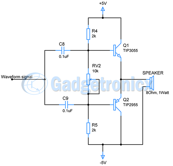
This amplifier is based on a complementary push pull amplifier since it has positive rail to negative rail inputs. The circuits uses complementary transistor pair TIP2955 ( PNP ) and TIP3055 ( NPN ) to operate.
A coupling capacitors C8 and C9 removes the DC components in the incoming signal. A resistor voltage divider network using R4, R5 and RV1 sets the bias point of both the transistors.The transistors should be set in cut off operation mode using RV2 since it will remove the quiescent current draw by transistors when there is no input signal.
When positive cycle of incoming signal fed into the circuit, Q1 conducts and Q2 will be in off state. Q1 collector current flows in this instant. The positive cycle will be exhibited in the output. Whereas during the negative cycle, Q2 conducts and Q1 will be off. The negative cycle will be exhibited in the output.
The reproduced waveform in the output will drive the speaker since it has sufficient current. This will produce a sound similar to the note.
Go nuts with the push buttons 😛
NOTE:
- The signal frequencies from piano notes were chosen as reference for designing this audio synthesizer. This circuit cannot generate sound similar to a piano.
- The usage of +5V and -5v with the above circuit is necessary.
- You can add more capacitors and buttons with COSC pins for generating more musical notes within MAX038 capabilities. Use the mentioned formula under “Fixing capacitor values” section to make the cap selection.


did you use log pots or linear pots for the ones in the piano key synth . So you can add a pot instead og 12k for the REF segment?