
Backup power supplies have become a necessity these days since we cannot afford interruption in our routine. You might have seen pretty sophisticated version of this Backup circuit in Office, hospitals and sometimes at residential areas. Leaving the sophisticated backup setup it’s pretty easy to build a simple one for yourself that can operate your appliances without interruption.
RELAY:
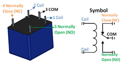
Relay is an electromagnetic switch that performs the switching using electromagnetism. It consists of an inductor coil, which acts as electromagnet here which attracts the pole which results in turning the device connected to it. When the coil gets demagnetised it releases the pole turning the device off . The type of relay switch used in this circuit is Single Pole Double Throw (SPDT) switch. The schematic diagram and pin out Configuration of a SPDT relay is shown above.
AUTO BACKUP CIRCUIT DIAGRAM:
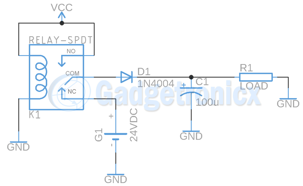
The circuit starts with Relay with 24v supply powering up the relay coil and our load is connected to NO pin of the relay through a diode and Capacitor. Meanwhile a 24v battery which is going to act as our back up supply is in contact with NC pin. When the load is connected to the VCC terminal supply voltage, the inductor coil in the relay gets energised and the coil acts like a magnet which attracts the pole at COM terminal towards NO terminal. This connects the device to 24v supply and power the load.
When the power goes off, VCC supply goes off and coil gets discharged. Now the coil doesn’t act like a magnet, here pole will switch to NC where 24v battery is connected. When the power comes back on VCC flows back into Relay, Inductor coil gets energised and powers the load.
Relay is considered to be slow with high switching time so we have added a decoupling capacitor C1 in the output stage. This will keep the device from turning off when the Relay pole makes the switch from NC to NO terminal and vice versa. A diode is added before Capacitor to prevent reverse flow of current from Capacitor back to relay or the battery.
As you can see when supply stops from one source, relay switches to backup supply from another source. Thus this circuit enables uninterrupted supply to the load and in turn keeps the appliances all the time.
APPLICATIONS:
- Power systems
- Hospital equipment
- Electronic devices
Hope this circuit was useful to you. If you have any queries leave them in the comments section below we will answer them. Do check out other Power circuits in our website.


Thank you