Linear voltage regulators are most popular due to their low price point and availability. 78xx is a popular series of linear voltage regulators that’s available for various output voltage ranges such as 5V, 6V,9V, 12V and so on. But there are also a 79xx series of linear regulators that delivers negative voltage as output. This circuit uses 7805 and 7905 linear regulators to to give output voltage of +5V and -5V respectively.
WORKING OF CIRCUIT:
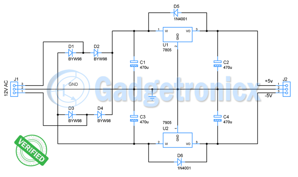
The circuit is supplied with 12V AC signal. Use a center tapped 12-0-12V / 2A step down transformer to power this circuit. The AC signal is then passed to a full wave bridge rectifier using diodes BYW98 which has a fast recovery time . This removes the negative half cycles of a AC signal.
These four diodes serves as a rectifier and connected in a bridge rectifier configuration. A capacitor of 470uF smooths the alternating signal and feed a DC input voltage to both the chips 7805 and 7905.Notice the difference in polarity between smoothing capacitors connected to 7805 and 7905. Ensure to connect positive of C3 to ground and negative to input pin of 7905.
7805 and 7905:
Take a look at some important conditions that we need to satisfy in the design for 7805 and 7905 to work effectively. The input voltage to both the chip should be more than 2V of its output voltage as per its datasheet (3V will be ideal ). Also choose a transformer that can deliver 2A in its output. This affects the output current delivered by 7805 and 7905 since they are capable of delivering 1.5A to load.
Being a linear regulator 7805 and 7905 drops necessary input voltage to derive +5V and -5V respectively in its output. A decoupling capacitor C3 is used to provide uninterrupted output just in case if there is any drop in output voltage of 7805 and 7905 in case of power failure. Moreover it will further stabilize the output voltage from these two regulators.
Usage of diodes from output to input of these regulators is necessary. This is because when there is interruption is power supply voltage from regulator drops. This will force current from Capacitor to flow into regulator output. This will damage the internal transistor and may cause the component to fail. Adding diode provides a current low resistance current path for capacitor current to the input thus preventing regulator from any damage.
HEAT SINK:
Remember to add heat sink to both the linear regulator ICs since both of these dissipate about 7Watts in power. The IC can get really hot and fail if you fail to add heat sink with it.
Check out other power supply circuits in our website. Please use the comment box below if you have any queries or feedback about this circuit.
I agree with the switching and the use of smaller caps but if you do use a cap over 100uf the diode is there to protect the regulator from momentary shorts.But honestly I would use smaller tantalum caps.
This circuit doesn’t work. U2 overheats. The negative output (Pin 3 of U2) is not DC and is only 3V. If U2 pins 1 & 2 are reversed, a normal output is obtained. Diode D5 & D6 are not needed, and C2 & C4 can be just .1 uF. Be careful, C1 & C3 are electrolytics, so make sure that the pos. side of C3 is connected to ground because the voltage into U2 is negative wrt ground..
Please advise why your circuit works.