
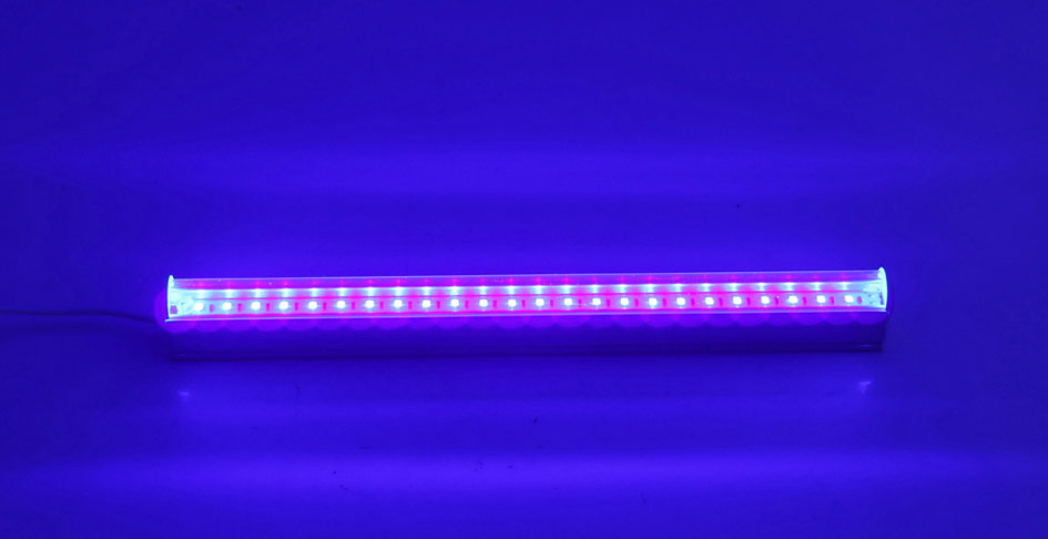
In times like these it’s important to take measures to sterilize or disinfect surfaces or things we interact with daily. Applying sanitizer or lotions may not be a viable solution in many circumstances. Did you know Ultraviolet lights of certain wavelength have germicidal properties ? Yes they are capable of destroying the virus, bacteria or other pathogens it comes in contact with. I have designed a UV disinfectant lamp circuit that uses special UV LEDs which is capable of emitting light at germicidal wavelength.
This circuit is powered by a NiMH battery and therefore portable for our convenience. To charge the battery we are going to use a Solar panel power and a charge controller to efficiently charge the battery.
UV-C LEDS:
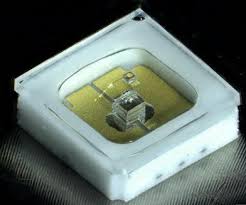
Let’s take a look at the most important part of the circuit – the Ultraviolet or UV LEDs. In this circuit we have to use a special LED’s called as UV-C LED’s which is capable of emitting UV light which is germicidal in nature. The germicidal UV light wavelength ranges from 100nm to 280nm. This UV light is capable of affecting the DNA of bacteria and virus hence destroying them in the process. Only UV-C LEDs are capable of producing UV light within this wavelength.
One such example is CL7001C3 which emits UV light of 275nm wavelength and suits perfectly for our purpose. I have based the circuit design using this LED. This LED has a forward voltage of about 5.2V and maximum current of 50mA.
BATTERY DISCHARGE PROTECTION & UV DISINFECTANT LAMP :
The circuit is powered using a NiMH battery pack of 6 cells which gives 7.2V and has a capacity of 2100mAH. NiMH has high energy density and therefore it weighs less. Moreover it’s quite easy to charge and doesn’t need complex circuits. Since this circuit is powered using a battery it’s important to use a discharge protection mechanism to prevent abusive usage of battery.
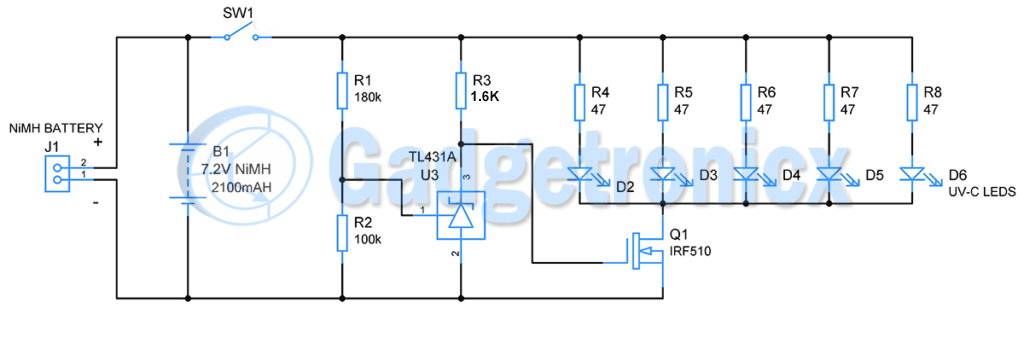
Figure 1: UV lamp circuit with battery discharge protection
The discharge protection mechanism comprises of R1, R2, R3 and U3 from figure 1. TL431 (U3) is a shunt regulator which can be set to deactivate the MOSFET Q1 when input voltage falls below a particular level.
Voltage across a single NiMH cell will be 1.4V when fully charged whereas during discharge it drops down to 1.15V when 80% of its capacity is consumed. This means for our battery pack of 6 cells the voltage will drop to ~6.9V approximately when 80% of battery capacity is consumed. This is the point where we need our battery to cutoff from our load that is UV LEDs.
For this purpose we are using TL431 ( U3 ) which is a shunt voltage regulator. But unlike regular shunt regulators, we can adjust its output voltage from 2.5V to 36V by feeding appropriate voltage in its 1st or ADJ pin. Our requirement of 6.9V falls right within this range. Also a regulation current of 1mA to 100mA should be supplied to its pin 3 in order to obtain this regulation. A voltage divider network R1 and R2 is used to set the voltage at ADJ pin. These resistor values can be calculated using the below formula as we know the regulation voltage already.
Vo = ( 1+ R1 / R2 ) x Vref
Let’s fix R2 = 100k. Vo is our cutoff voltage 6.9V and Vref is 2.5V which is internally fed to TL431. Substituting the known values
6.9 = ( 1 + R1 / 100k ) x 2.5V
R1 = 176k, we choose the closest value R1 =180k
Now voltage across pin 3 of TL431 is fixed as 6.9V. This activates the N channel MOSFET Q1 IRF510 thus in turn lights up the UV-C LEDs. When the battery is fully charged, voltage across NiMH battery will be around 8V and as the LEDs consume current voltage drops down. When 80% battery capacity is consumed battery voltage drops below 6.9V.
Now voltage output from voltage divider R1 and R2 falls below 2.5V which is the reference voltage of TL431. At this state TL431 will no longer regulate voltage and gate terminal of Q1 will be pulled low and LEDs will turn off. This is how the battery discharge mechanism protects the battery from over usage and helps sustain the battery cycles.
UV DISINFECTANT LAMP UNIT:
As mentioned before UV-C LEDs have a forward voltage of 5.2V and 50mA forward current. A 47ohm resistor is connected with each LED to limit the current to 50mA. When Q1 turns ON, current will flow from drain to source of Q1 thus turning these LEDs ON. These 5 LEDs will draw a total of about 250mA from the battery. TL431 will consume roughly about 22mA when battery voltage is at its peak. Summing these together this UV disinfectant circuit will draw about 280mA of current from battery. This is about 0.13C of its maximum capacity.
SOLAR POWERED NiMH BATTERY CHARGER:
This charge controller unit draws current from solar panel and charges the NiMH battery pack. Also this unit will stop the current flow when battery is sufficiently charged.
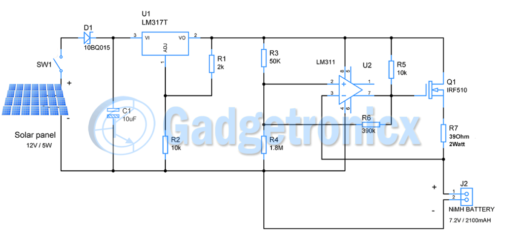
Figure 2 ; Solar powered NiMH charger with charge controller unit
NiMH batteries can be fast or slow charged. Fast charging is usually done by charging the battery by applying its maximum current capacity C or sometimes in multiples of C. Whereas slow charging can be done by supplying current at slow rates such C/5 or C/10. C/10 is mostly recommended when comes to slow charging to obtain maximum charge cycles in a battery.
In this circuit NiMH is going to charged slowly at the rate of 210mAH close to C/10. I have a 12V/ 5Watt solar panel which exhibits 11.5 to 11.9v and supply close to close to 420mA current at optimum conditions.
A Schottky diode D1 is used to prevent reverse flow of current from Capacitor when voltage drops across solar panel due to cloudy weather or during night. This diode has low voltage drop about 0.2v, therefore suits our purpose. The Capacitor is used to stabilize the voltage from solar panel.
LM317 an adjustable voltage regulator is used to regulate the input voltage from solar panel to 8V. We will be charging the battery at 8V since a fully charged NiMH cell will exhibit 1.3 to 1.4V which equates to an acceptable charging voltage range of 7.8 to 8.4 for 6 cells. We choose to charge it at 8V. Output of LM317 is governed by the formula
Vo = Vref ( 1 + R2 / R1 ) + IAdj x R2
We need Vo to be 8V. Fixing the Resistor R2 as 10k will help us to determine value of R1 and IAdj is 50uA as per the datasheet
8 = 1.25 ( ( R1 + 10k ) / R1 + 0.5
6 = ( R1 + 10K ) / R1
6R1 = R1 + 10K
R1 = 2K
Here LM317 will drop about 4v from Solar panel to bring it to 8V. It also supplies a current of 220mA approximately to the circuit. This will force the regulator to dissipate more than 1 Watt. Therefore it is advised to add a heat sink to this regulator.
CHARGE CONTROLLER:
A comparator chip LM311, R3,R4, R6, R5 will decide whether the battery need to be charged or it is sufficiently charged enough. The comparator activates the output MOSFET. The voltage input from battery is fed to inverting terminal of comparator. In the non inverting terminal a voltage divider of R3 and R4 is built to feed reference voltage. In addition to this a feedback resistor R6 is added to provide hysteresis.
Adding hysteresis will help comparator to eliminate false triggering of comparator. To add hysteresis we have to setup a high and low threshold voltage. High threshold voltage determines the point at which the battery needs to stop charging. Low threshold voltage determines the point at which the battery needs to start charging.
I have chosen the high trigger voltage to be 7.8 since we need to charge the battery as close to 8V as possible. On the other hand low trigger voltage as 6.9 since NiMH when discharged to 80% of its capacity drops the voltage to 1.15 per cell. This equates to 6.9 for 6 cell NiMH battery pack.
In order to set these voltages we need to fix the value of Resistor R3, R4 and R6.
Using these two formulas we can determine the resistor values
R6 / R3 = VL / ( VH – VL ) & R4 / R3 = VL / ( Vcc – VH )
Substituting the threshold values
R6/ R3 = 6.9 / ( 7.8 – 6.9 ) = 7.6
R6 = 7.6 x R3
R4 / R3 = 6.9 / ( 8 – 7.8 ) = 34.5
R4 = 34.5x R3
Let’s fix R3 as 50k
R6 = 380k and R4 = 1725k
Fixing the standard values for these resistors
R6 = 390k and R4 = 1.8M
Now we have fixed the values and provided hysteresis to activate and deactivate the comparator. When battery is set to charge, when it close to reach about 90% of its maximum capacity voltage across it exceeds 7.9V. This is fed to inverting terminal of comparator. This forces the comparator output to low state. This turns off the N-channel MOSFET connected to it. This stops the flow of current to battery ceasing the charging process.
Let’s consider discharging scenario. When battery charge is utilized up to say 80% then voltage across it will drop below than 6.9V. This triggers non inverting input of comparator. This forces the output to go high. Now the MOSFET will turn ON allowing current to flow through it and thus charging the battery.
Also when battery voltage exceeds 7V due to charging the comparator will continue to force the MOSFET to charge the battery due to hysteresis. This continues until the battery voltage exceeds high threshold of 7.9V. Once high threshold is breached charging ceases. When battery voltage drops to say 7.6V after consuming 50% of its capacity, Comparator will not charge the battery until it drops below 6.9V.
A resistor R7 of 39Ohm is used in series with battery to limit the current flow to 210mA. This is to charge the battery at C/10. Remember to use resistor of 2Watt as it dissipates 1.6W due to charging current of the battery.
CHARGE AND USAGE TIME:
The Circuit is set to charge the battery from Solar panel at the rate of 210mA which is about 0.1C. This takes about 10 hours to reach its maximum capacity of 2100mA. During lamp usage it consumes roughly around 280mA. The lamp can be used until 80% battery capacity is utilized which is 1680mA. Therefore this lamp can be used for 6 hours.
PARTS REQUIRED:
A) Battery discharge protection and UV disinfectant lamp circuit
- SPST switch – SW1
- R1 – 180k
- R2 – 100k
- R3,R4, R5, R6, R7, R8 – 47 Ohms
- U3 – TL431A
- Q1 – IRF510
- B1 – 7.2V / 2100mAH NiMH battery
- J1 – 2 pin connector
B) Solar powered NiMH battery charger circuit
- Solar panel – 12V / 5Watt
- D1 – Schoktty diode 10BQ015
- U1 – LM317T
- C1 – 10uF
- R1 – 2k
- R2, R5 – 10k
- R3 – 50k
- R4 – 1.8M
- R6 – 390k
- Q1 – IRF510
- R7 – 39Ohm, 2Watt
- J2 – 2 pin connector
FUTURE IMPROVEMENTS:
- We can increase the number of LEDs to increase the range and effectiveness of UV lamp using the same battery as NiMH typically can safely discharge up to 1C.
- Add a low power LED as an indicator in UV lamp circuit to show when the battery reached cut off state indicating the need to charge.
- Use Solar panels of high wattage to increase the rate of charging of NiMH battery
NOTE:
- UV-C light can be harmful to humans, avoid exposing to your skin or any other body parts. It is meant to use of surfaces and water.
- All the resistors used in both the circuits are of 1/4 Watt unless specified otherwise
- If you wish to use a different battery with this circuit, perform all the mentioned calculations to fix the part specifications tailored to this circuit
This project will certainly help in staying away from infection and protect ourselves. If you have any improvement ideas or feature additions to this project, do leave them in the comments section below. Feel free to ask your queries, I will answer them. Happy DIY 🙂


I’ve been able to take a 5w UVC bulb, connected via G23 socket, connect to ballast and connect directly to a 50w solar panel. When the sun hits, the bulb lights, which means I am emitting UVC rays to kill the mildew and bacteria in my remote RV without the need of a battery.
Can you make a pool floating solar uv light and will it work?