A few years ago, a client was making a device that ran on a Lithium ion, Li-Ion poly, Li-Po, battery that was nominally 12V. Li-Po batteries can be damaged if they are discharged below a critical level. In this case the safe threshold was 10.8V. I designed a battery discharge protection for circuit for Li-ion and Li-Po batteries that could be turned ON or OFF using two push-buttons and most importantly would cut OFF the load current when the battery voltage reached the 10.8V threshold.
An important feature of the design was that when the load current was turned OFF, the only current that was drawn was the leakage current of the power MOSFET Q3 and the collector leakage current of transistors Q1 and Q2. These currents are so low that the battery’s internal leakage is higher.
Working of Li-ion and Li-Po battery discharge protection circuit :
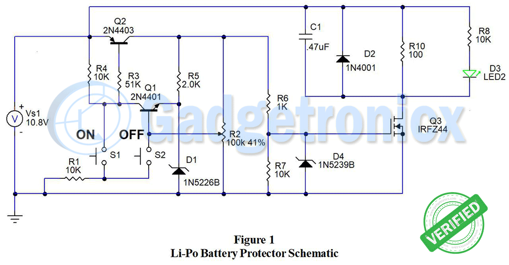
Please refer to the schematic in Figure 1 for the following discussion of the circuit’s operation. When switch S1 is pressed, transistor Q2 is turned ON by R3 and R1 to ground. This applies the battery voltage to three branch circuits. Branch 1 consists of resistor R5 and zener diode D1. They form a voltage reference for the emitter of transistor Q1. Branch 2 is trim potentiometer R2, that provides voltage feedback to the base of Q1. Branch 3 is voltage divider R6 and R7 which drive the gate of power MOSFET Q3.
ON and Cut off state:
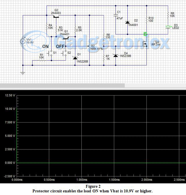
When the battery voltage of Vs1 is 10.9 volts or higher, the wiper voltage of R2 exceeds the reference voltage to the emitter of Q1 by .6V and thus, Q1 is ON. Transistor Q1 latches Q2 ON. This in turn activates Q3 which drives the load. Figure 2 shows the circuit latched ON when battery Vs1 is 10.9 volts or higher.
OFF state:
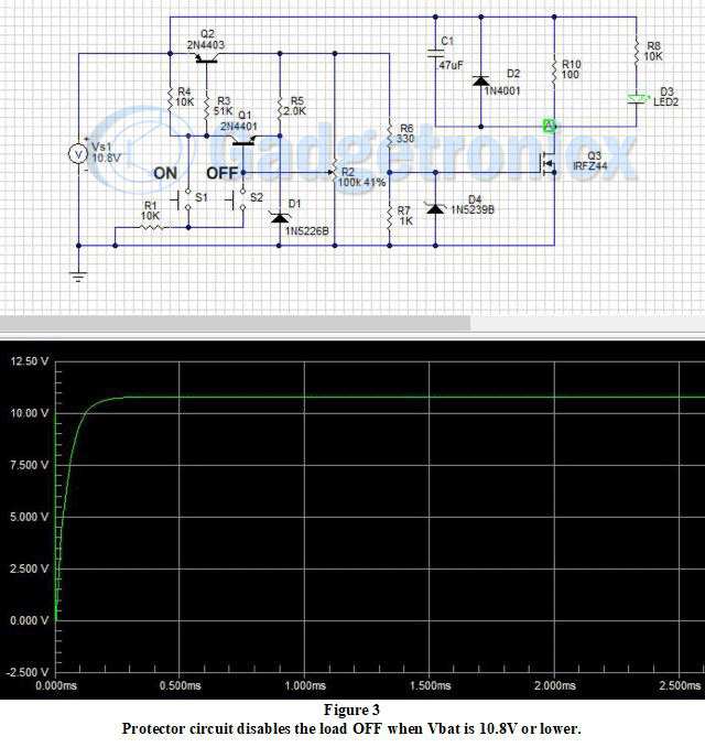
When the battery voltage of Vs1 is 10.8 volts or lower, the wiper voltage of R2 is less than Q1 + .6V and Q1 turns OFF. Resistors R11 and R3 turn OFF Q2, which cuts OFF the voltage to Q1 and power MOSFET Q3 as shown in Figure 3 above. Thus, no current flows except for the leakage current of Q1, Q2 and Q3. These are typically in nano-amps. This design is a true cut-off to protect the Li-Ion poly, Li-Po, battery.
Some additional features include GRN LED, D3, that shows when power is being supplied to the load. Diode D2 suppresses voltage spikes due to inductive loads such as a motor or relay coil. Capacitor C1 was added to reduce brush noise from a motor.
Diode D4 was included to prevent damage to the gate of MOSFET Q3 when the Li-Po battery voltages are above 9.1V. The load is shown as R10, can be any device so long as it does not exceed the current ratings for the Li-Po battery.
Potentiometer R2 means that the cut-off circuit can be adjusted for any cut-off voltage from 3.3 to 30 volts. To set R2, connect the cut-off circuit to the load. Connect the cut-off circuit battery connection to an adjustable power supply. Set the power supply voltage to the cut-off voltage desired.
Press the ON button and adjust R2 until the GRN LED stays On when you release the ON button. Slowly adjust R2 until the GRN LED turns OFF. Turn the supply voltage up and press the ON button, the GRN LED should stay ON. Slowly turn down the supply voltage. The GRN LED should turn OFF at the calibrated voltage used to set R2. You may need to finesse the adjustment to get it to the exact value you desire.
When the Li-Po batteries are charged, the ON and OFF push-buttons can be used to turn the connected load ON or OFF as needed.
Note:
You’ll notice that the values for R6 and R7 are different in the simulation schematics compared with the BOM. The reason is that the SPICE simulation software gave incorrect results with the higher resistor values listed in the BOM. MOSFET Q3 was ON when it should have been OFF.
When the actual circuit was built, the higher value resistors worked fine. This is a good example of how mathematical models can behave differently than actual hardware. Keep that in mind when designing and simulating circuits.
PCB design:
Figure 4 shows the PCB layout. Added the Gerber files below. You can download them and build this project through your favorite PCB manufacturer.
Gerber files to order Lithium ion and Lithium polymer battery protection circuit
Languages:
English
Author:
Ron Hoffman
Platforms:
Windows 8
Requirements:
Gerber viewer
Category:
Project Files
License:
Shareware
Date:
October 11, 2020
Bill of Materials:
The BOM provides a list of the components for the Li-Po Battery Protector circuit. Hope everyone finds a good use for this circuit.
Item
Quantity
Reference
Description
1
4
R1,4,7,8
10K, 1/4W, 5% carbon film resistor Yageo or equivalent
2
1
R2
100K, 6mm cermet trimmer potentiometer.
3
1
R3
51K, 1/4W, 5% carbon film resistor Yageo or equivalent
4
1
R5
2.0K, 1/4W, 5% carbon film resistor Yageo or equivalent.
5
1
R6
1K, 1/4W, 5% carbon film resistor Yageo or equivalent
6
1
C1
470 nF , 50V film or ceramic capacitor.
7
1
D10
1N5226B, 3.3V, 500mW, zener diode or equivalent.
8
1
D2
1N4004, 1amp, 400 PIV diode.
9
1
D3
Green LED, T-1, 3mm
10
1
D4
1N5239B, 9.1V, 500mW, zener diode.
11
1
S1,S2
5mm N.O. push-button switch, EVQ-PAC09K, or equivalent.
12
1
Q1
2N4403, 2N2907A, PN200, 40V, 500ma, PNP transistor, or equiv
13
1
Q2
2N4401, 2N2222A, Pn=N100, 40V, 500ma, NPN transistor, or equiv.
14
1
Q3
IRFZ44 40V, N-channel MOSFET, TO-220
15
1
PCB
HOFFMAN ELECTRONICS INC. See Gerber files
Try out this project and save your Lithium batteries. Comment your feedback and thoughts about this circuit below. Check out other Electronics projects in our website.

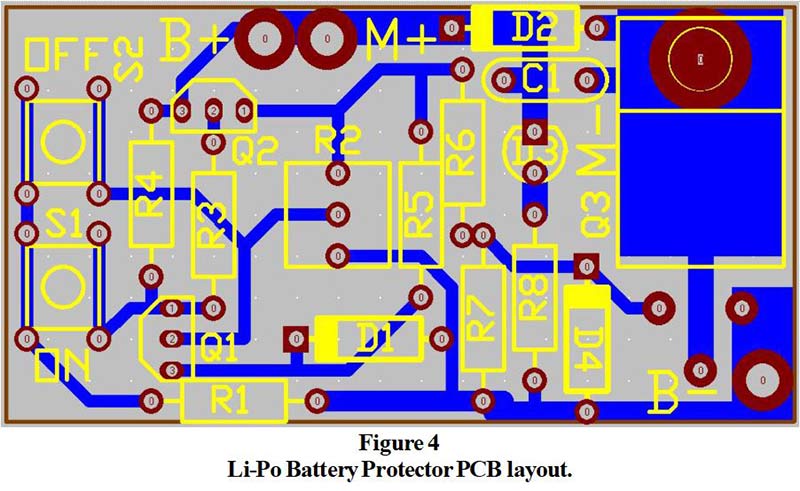


The PCB layout is wrong. LED Q3 is not connected to M- but instead to B-.
Besides that, I can’t get the circuit working.