Over the years I have designed and built many different types of Intercoms. I have a patent on a unit that uses piezoelectric discs as speakers for a door mountable intercom. The intercoms always required the user to operate a press-to-talk switch in order to communicate back and forth with the remote unit. This is cumbersome and annoying. This design eliminates the press-to-talk switch and eliminates feedback with unique sound cancellation circuitry. The units can be activated from either position with an ON-OFF switch.
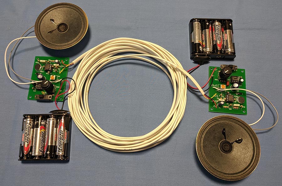
Picture 1: Switchless Intercom prototype with 50 feet of 4-conductor phone cord
Working of Intercom circuit:
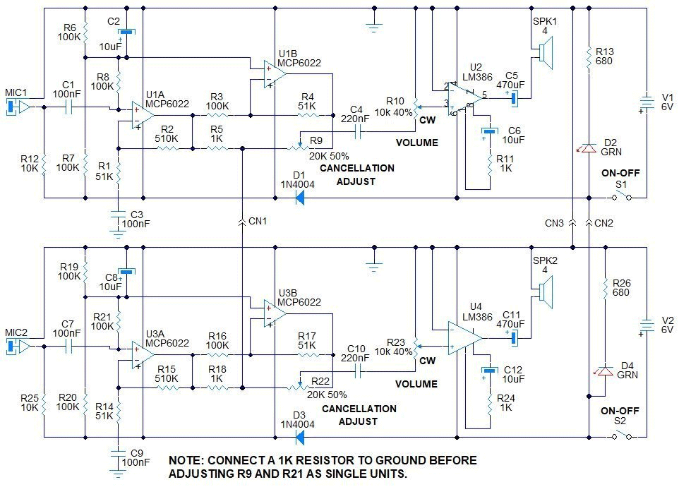
Figure 1 Schematic diagram
Please refer to the schematic in Figure 1 for the following discussion of the circuit description and theory of operation. The intercom consists of two identical units. They are connected via a three-wire cable that provides the audio signal, power, and ground between the two units, (CN1, CN2 AND CN3, respectively). The really cool part of the circuit is the noise cancellation by op-amp U1B, R3, R4, R5 and R9.
Resistor R12 provides phantom power to electret microphone MIC1. The audio signal from MIC1 is passed by C1 to the +input U1A. Resistors R6, R7, and C2, divide and filter the supply voltage in half. Resistor R8 functions as the input load and Vs/2 voltage reference to U1A. Resistors R1 and R2 provide feedback for U1A. That provides a gain of, G = 1 + R2 / R1 = 11. The output of U1A is connected to the noise cancellation circuitry. The +input of U1B is connected to the Vs/2 voltage reference. Resistors R3 and R4 provide the feedback for U1B. The gain, G = R4 / R3 = 51K / 100K = .5. This makes the output at U1A = -.5 times the output at U1B.
Sound cancellation:
The output of U1A is also connected via resistor R5 and trimpot R9 to the output of U1B. Resistor R5 (1K) when connected to the second unit that also has R17, 1K resistor, connected to the output of U3A. This causes the audio signal at the R5 – R9 node to be one half of the U1A level. Thus when trimpot R9 is adjusted to about half, the signal from Mic1 is canceled at the wiper of trimpot R9. Any sound created from SPKR1 back to MIC1 is cancelled. However, any signal from unit 2, the output of U3A, is not cancelled and comes out at SPKR1.
The same is true in reverse, i.e., the sound created from SPKR2 to MIC2 is cancelled at the wiper of trimpot R21, but the sound from the first unit is amplified and emitted from SPKR2. Thus each unit sends its sound to the other unit, while cancelling any feedback from the unit’s speaker output. The LM386 audio amplifier, (U2), receives the audio signal from the wiper of trimpot R9, through C4 and volume control R10. Capacitor C6 and R11 set the maximum gain for the LM386. Capacitor C5 connects the output of U2 to SPKR1 while blocking DC voltage.
Turning the unit ON/OFF:
Switches S1 (unit 1) and S2 (unit 2) enable the battery of either or both units to be powered ON and OFF. This enables the users to power the intercom ON or OFF from either unit. Both switches must be OFF to shut OFF the intercom. If only one battery is connected, this allows that unit to be the only unit capable of turning the intercom ON and OFF. This may be desirable for privacy considerations. The green LEDs show when the units are powered and working to let the user know when one of the ON-OFF power switches is ON. This not only lets you know if someone is listening in on you and alerts you to turn OFF both units to prevent running down the batteries when the intercom is not needed.
PCB design:
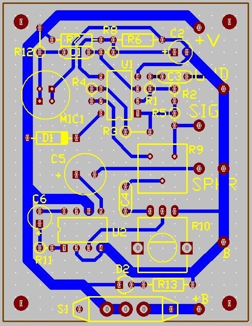
Figure 2 shows the PCB board layout. Gerber files are provided if you want to use a PCB build this project. This can also be easily be made using point-to-point wiring on a .1″ x .1″ perf board such as a Radio Shack # 2760147.
Figure 2
Note that the circuit board layout is single sided. If you wish to mount the electrolytic capacitors on the bottom side of the board to facilitate mounting the board to the enclosure panel, you should order a double sided board so that the component pads will be plated through and allow soldering from either side. You can download the Gerber files for above PCB below. You can use services like JLCPCB to get your PCBs ordered, they have quick turn around time and produce high quality PCBs.
Battery pack holder, 4-AA or 4-AAA battery pack with 9V battery terminals.
21
8
BTRS
AA or AAA batteries.
Hope this project was useful to you, try this out for yourself. If you have any queries, feedback kindly post them in comments section below and I will answer them.
Hi Ron, Its showing it will work upto 50 feet. Can we use it above 50 feet like 500 meters with some modification like power supply in place of battery or something else. Can we use line matching transformer as well for more distance.
Hii Ron thanks for your help in this
Please may I know if you can share the literature survey and project report of this then it will be very helpful for us to design this
very interesting project ron. I suggest you to make a video about the results of your project. show us how the results of this project have been achieved so we can be sure.. thank you
Rudy, You saw the pictures, the PCB layout, the schematic, the description. It works fine. The article shows the results. A video takes too much time memory and bandwidth. The technique used is the same as in telephones to prevent feedback from the mic to the earphone speaker, while sending the full signal out to the network. Hope you liked the article. Build it and see for yourself. Regards, Ron
On the diagram you state, ‘connect a 1k resistor to ground…’ Where does one connect the resistor? From where to ground? Also, the LM386 is notorious for instability and I would thoroughly recommend that a snubber circuit is added on the output, something like a 10 ohm resistor in series with a 47nF capacitor from pin 5 to ground. Using a somewhat higher impedance speaker also helps, 16 ohms is good. A 100uF capacitor across the supply will decouple and also help stability, especially when the battery is running down.
Hi Ron,
I built your circuit and as roland rightly suggested, i had to add a snubber circuit from pin 5 to ground to improve the stability of the LM386.
Despite this, I encounter the following problems :
– The output sound level is very low!
– You have to speak very close to the microphone to be able to hear something in the other speaker.
In addition, the sound output from the 8 ohm speaker is poor and is of a metallic type I increased the impedance of the loudspeak by adding another one in series (16 ohm as suggested by Roland) and the sound quality has improved.
I would like some advice to solve the problems highlighted.
Hi Aniello, Make sure you use a 470 uF electrolytic cap on the output of the LM386 or it will sound tinny. The 10 uF and 1K cap on the LM386 provides for a gain of 200. The LM386 is only slightly unstable at lower gains. Make sure R9 is adjusted only to cancel out the sound from the units mic. to adjust it properly, connect a 1K resister from the junction of R5 and R9, (the input signal, designated CN1) to ground. Turn the gain up high, then adjust R9 until the feedback is gone. Do this for both units. Then connect them. If they are too close, they will feed back. Put one in another room so that you can turn up the volume without feedback. Realize that the farther away from the microphone you are, the lower the sound output will be. You should be within 1 to 3 feet of the microphone. Hope this helps you out. Regards, Ron Hoffman
HI Aniello, The speakers I used were 8 ohm units. I think 4 ohm speakers would cause a tinny sound due to the impedance of the 470 uF cap. Just doing the quick math, the roll-off frequency is Fo = 1/(2*pi*R8C) = 1/(6,2832*4*.00047) = 84 Hz. For an 8 ohm speaker, Fo = 1/(6.2832*8*.00047) = 42 Hz. Also, the current drain with 8 ohm speakers is less which reduces any instability due to power fluctuations. Regards, Ron Hoffman
Aniello Maresca
Hi Ron,
I did what you suggested .. but unfortunately the same problems that I have pointed out to you always remain.
The sound cancellation function works well.
In order to hear something, I have to speak at a distance of less than 0.5 feet (15 cm)
from the microphone.
I made the circuit like the one you published, the only difference is that I have not used the battery but a transformer, rectifier bridge, capacitors and LM78S06 regulator.
Each circuit is powered the same way, and I connected the two circuits with only two wires : CN1 and GND.
The kind of electret microphone you used could be the problem. If you have an old one, they lose sensitivity. I had one in a guitar tuner that lost it’s sensitivity after many years. The tuner couldn’t “hear” my guitar when tuning. I replaced it and it works like new. High humidity can cause the electret element to lose sensitivity. Try using a different type of electret mic, or new one and see if that works. The mic pre-amp gain can be increased by increasing the 510 K resistor to 1 Meg or 2.2 Meg. Also, make sure you are using the MCP6022 op-amp for the mic and noise cancelling amps. It has very high impedance CMOS inputs. An LM358 will not work. Try these things out and see how they work.
Ron Hoffman
Hi Roland, If you read the note on the schematic, the 1K resistor to ground is only used toa adjust the cancellation pots R9 and R22 when the units are being individually adjusted. The 1K would be connected from the signal input of the unit to ground. The signal input is the junction of R5 and pot R9, or R18 and R22 on the second unit. I built the project and had no problem with LM386 Stability when used in the 200 gain configuration. A 100 uF cap from +V to ground on each unit would help with current peaks, but isn’t required. My switchless intercom works fine as shown using the PCB indicated. Short lead runs eliminate much of the noise and instability. Also, using the 470 uF output cap increases the low frequency drive to the speaker.
Thanks for the reply. A small point but there’s an error either on the diagram or the PCB layout. You have the diode on the diagram supplying everything other than the 386 but the board shows R7 and R12 supplied from V+, before the diode. I doubt it makes a lot of difference, though. Why use the diode at all? To drop the supply voltage to less than the 7V max rating of the opamp when using new batteries?
And why, oh, why did you draw the schematic upside down? Is that just to upset people like me in the southern hemisphere? 😉 I’m in Johannesburg, South Africa standing on my head.
One other point is that I haven’t had a chance to breadboard this yet but I’m planning to use the LM4562 dual which is not rail to rail and nor is it a fet input type. But I don’t see any reason why it shouldn’t work. I haven’t come across the MPC6022 before, very nice chip except for the supply voltage limitation. The LM4562 is also excellent and since I was sent 50 free samples (Yes, really) I’ll give it a go.
This is a very interesting circuit, thanks, and something I’ve had lurking in the back of my mind for years, the problem of overcoming howl-round.
Roland.
I’m not sure Naseer, but it would be easy enough to connect thre units and see how it works. The only modification might be the value of the connecting signal out resistor. Try it and let me know how it works. Regrds, Ron Hoffman
Hi Ron,
Your project is great. I was thinking I could use it as a new door phone for my parents’ house.
I just have one doubt. I fear there could be a problem with the outdoor unit. It must be handsfree so I think the sound from speaker will feed the mic, going towards the inside speaker: this way the person talking from the inside unit would hear his/her voice in the speaker without any attenutation.
What I mean is that the circuit prevents sound from mic of one units to reach the speaker of the same unit, but doesn’t really solve the echo cancellation problem for the external unit.
Am I right?
Thank you so much,
In the description you will notice that the adjustment of the cancellation control eliminates the feedback you are thinking about. The signal from the inside unit is amplified and output to the speaker. The mic picks up that output and amplifies it. Normally that would cause a problem, but in this circuit, the signal is inverted 180 degrees out of phase with the original signal and thus cancels the feedback. The same is true for the outside signal going inside. The combining control is adjusted so that the feedback signal, (speaker-to-mic), is cancelled by the incoming signal. In fact it works best when the speaker and mic are positioned fairly close together. The sound cancellation section of the article explains this. If the circuit is powered by a wall transformer. The unit can be turned ON or OFF from either side.
Thanks Kevin. I put the boards speakers and battery packs into plastic enclosures. I connected the two units with a 3-conductor cable with 3.2 mm stereo plugs on each end. They plug in easily. After adjusting the noise cancellation pots, the units worked great. Let me know how it works if you build it and send me pictures of your completed project. Regards, Ron.


Hi,
I am looking for push to talk intercom so can i Use this circuit, also I want intercom to operate on 12 / 24 V so what modifications required
Hi Ron, Its showing it will work upto 50 feet. Can we use it above 50 feet like 500 meters with some modification like power supply in place of battery or something else. Can we use line matching transformer as well for more distance.
Hi,
How long can be the cable between both units ? Can be up to 100m ?
Hii Ron thanks for your help in this
Please may I know if you can share the literature survey and project report of this then it will be very helpful for us to design this
very interesting project ron. I suggest you to make a video about the results of your project. show us how the results of this project have been achieved so we can be sure.. thank you
Rudy, You saw the pictures, the PCB layout, the schematic, the description. It works fine. The article shows the results. A video takes too much time memory and bandwidth. The technique used is the same as in telephones to prevent feedback from the mic to the earphone speaker, while sending the full signal out to the network. Hope you liked the article. Build it and see for yourself. Regards, Ron
On the diagram you state, ‘connect a 1k resistor to ground…’ Where does one connect the resistor? From where to ground? Also, the LM386 is notorious for instability and I would thoroughly recommend that a snubber circuit is added on the output, something like a 10 ohm resistor in series with a 47nF capacitor from pin 5 to ground. Using a somewhat higher impedance speaker also helps, 16 ohms is good. A 100uF capacitor across the supply will decouple and also help stability, especially when the battery is running down.
Hi Ron,
I built your circuit and as roland rightly suggested, i had to add a snubber circuit from pin 5 to ground to improve the stability of the LM386.
Despite this, I encounter the following problems :
– The output sound level is very low!
– You have to speak very close to the microphone to be able to hear something in the other speaker.
In addition, the sound output from the 8 ohm speaker is poor and is of a metallic type I increased the impedance of the loudspeak by adding another one in series (16 ohm as suggested by Roland) and the sound quality has improved.
I would like some advice to solve the problems highlighted.
Thanks so much.
Aniello
Hi Aniello, Make sure you use a 470 uF electrolytic cap on the output of the LM386 or it will sound tinny. The 10 uF and 1K cap on the LM386 provides for a gain of 200. The LM386 is only slightly unstable at lower gains. Make sure R9 is adjusted only to cancel out the sound from the units mic. to adjust it properly, connect a 1K resister from the junction of R5 and R9, (the input signal, designated CN1) to ground. Turn the gain up high, then adjust R9 until the feedback is gone. Do this for both units. Then connect them. If they are too close, they will feed back. Put one in another room so that you can turn up the volume without feedback. Realize that the farther away from the microphone you are, the lower the sound output will be. You should be within 1 to 3 feet of the microphone. Hope this helps you out. Regards, Ron Hoffman
Thanks Ron,
i will do as you said.
I just wanted to ask you one more thing :
the speakers are 4ohm ?
I’ll update you on the result
Regards
Aniello
HI Aniello, The speakers I used were 8 ohm units. I think 4 ohm speakers would cause a tinny sound due to the impedance of the 470 uF cap. Just doing the quick math, the roll-off frequency is Fo = 1/(2*pi*R8C) = 1/(6,2832*4*.00047) = 84 Hz. For an 8 ohm speaker, Fo = 1/(6.2832*8*.00047) = 42 Hz. Also, the current drain with 8 ohm speakers is less which reduces any instability due to power fluctuations. Regards, Ron Hoffman
Hi Ron,
I did what you suggested .. but unfortunately the same problems that I have pointed out to you always remain.
The sound cancellation function works well.
In order to hear something, I have to speak at a distance of less than 0.5 feet (15 cm)
from the microphone.
I made the circuit like the one you published, the only difference is that I have not used the battery but a transformer, rectifier bridge, capacitors and LM78S06 regulator.
Each circuit is powered the same way, and I connected the two circuits with only two wires : CN1 and GND.
Do you have any other suggestions ??
Thanks and Regards
Aniello
The kind of electret microphone you used could be the problem. If you have an old one, they lose sensitivity. I had one in a guitar tuner that lost it’s sensitivity after many years. The tuner couldn’t “hear” my guitar when tuning. I replaced it and it works like new. High humidity can cause the electret element to lose sensitivity. Try using a different type of electret mic, or new one and see if that works. The mic pre-amp gain can be increased by increasing the 510 K resistor to 1 Meg or 2.2 Meg. Also, make sure you are using the MCP6022 op-amp for the mic and noise cancelling amps. It has very high impedance CMOS inputs. An LM358 will not work. Try these things out and see how they work.
Hi Roland, If you read the note on the schematic, the 1K resistor to ground is only used toa adjust the cancellation pots R9 and R22 when the units are being individually adjusted. The 1K would be connected from the signal input of the unit to ground. The signal input is the junction of R5 and pot R9, or R18 and R22 on the second unit. I built the project and had no problem with LM386 Stability when used in the 200 gain configuration. A 100 uF cap from +V to ground on each unit would help with current peaks, but isn’t required. My switchless intercom works fine as shown using the PCB indicated. Short lead runs eliminate much of the noise and instability. Also, using the 470 uF output cap increases the low frequency drive to the speaker.
Hi Ron,
Thanks for the reply. A small point but there’s an error either on the diagram or the PCB layout. You have the diode on the diagram supplying everything other than the 386 but the board shows R7 and R12 supplied from V+, before the diode. I doubt it makes a lot of difference, though. Why use the diode at all? To drop the supply voltage to less than the 7V max rating of the opamp when using new batteries?
And why, oh, why did you draw the schematic upside down? Is that just to upset people like me in the southern hemisphere? 😉 I’m in Johannesburg, South Africa standing on my head.
One other point is that I haven’t had a chance to breadboard this yet but I’m planning to use the LM4562 dual which is not rail to rail and nor is it a fet input type. But I don’t see any reason why it shouldn’t work. I haven’t come across the MPC6022 before, very nice chip except for the supply voltage limitation. The LM4562 is also excellent and since I was sent 50 free samples (Yes, really) I’ll give it a go.
This is a very interesting circuit, thanks, and something I’ve had lurking in the back of my mind for years, the problem of overcoming howl-round.
Roland.
Thanks for sharing your project Ron. Would I be able to connect a third unit to the system with no issues when all three units are powered on?
I’m not sure Naseer, but it would be easy enough to connect thre units and see how it works. The only modification might be the value of the connecting signal out resistor. Try it and let me know how it works. Regrds, Ron Hoffman
Hi Ron,
Your project is great. I was thinking I could use it as a new door phone for my parents’ house.
I just have one doubt. I fear there could be a problem with the outdoor unit. It must be handsfree so I think the sound from speaker will feed the mic, going towards the inside speaker: this way the person talking from the inside unit would hear his/her voice in the speaker without any attenutation.
What I mean is that the circuit prevents sound from mic of one units to reach the speaker of the same unit, but doesn’t really solve the echo cancellation problem for the external unit.
Am I right?
Thank you so much,
Mike
In the description you will notice that the adjustment of the cancellation control eliminates the feedback you are thinking about. The signal from the inside unit is amplified and output to the speaker. The mic picks up that output and amplifies it. Normally that would cause a problem, but in this circuit, the signal is inverted 180 degrees out of phase with the original signal and thus cancels the feedback. The same is true for the outside signal going inside. The combining control is adjusted so that the feedback signal, (speaker-to-mic), is cancelled by the incoming signal. In fact it works best when the speaker and mic are positioned fairly close together. The sound cancellation section of the article explains this. If the circuit is powered by a wall transformer. The unit can be turned ON or OFF from either side.
This is really a wonderful design!
Thanks Kevin. I put the boards speakers and battery packs into plastic enclosures. I connected the two units with a 3-conductor cable with 3.2 mm stereo plugs on each end. They plug in easily. After adjusting the noise cancellation pots, the units worked great. Let me know how it works if you build it and send me pictures of your completed project. Regards, Ron.