LED projects are always fun and fascinating. Recently I have been working with RGB LEDs and found it really addictive because of the endless possibilities of colors and easy configuration. I got this idea of making a Pixel stick or light wand which can light up in any possible color we can imagine and control it via local area network. This pixel stick was originally intended as a Light painting tool for photographers but its functionality is quite broader than that.
1. FEATURES OF PIXEL STICK:
In order to overcome the above two challenges I have added the below features:
WiFi Operated – This light painting stick can be controlled ( turned ON/OFF, Changing colors ) very easily using a simple browser within any WiFi enabled devices.
Standard colors – This stick is coded to emit standard colors like ( Red, Blue, Green, Gold, Rainbow, White ) using a simple button input.
Custom Colors – Apart from the standard colors this stick is quite capable of generating any color as per the wish of Photographer. It was added with a feature to input RGB code of any color as you wish like cyan,magenta, turquoise, olive, maroon etc. Look up for the “RGB color codes here” and use it to get your custom color.
2. MATERIALS REQUIRED:
Arduino Uno
LED strip (25 LED’s)
Power bank (5v, 10000mAh)
ESP8266 module
Bidirectional logic converter module
Connecting Wires
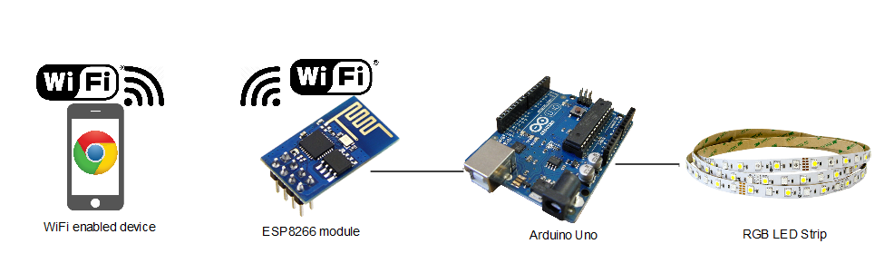
3. BLOCK DIAGRAM:
This Light painting project is based on the concept of IOT where two networking devices connect with each other to form a network in turn establishing communication and control. Here Arduino will host a webpage and act as a server. This webpage was designed in a way to take LED control inputs ( Colors : Red, Blue, Green and ON/OFF) from the user . This hosted webpage can be accessed via WiFi enabled device that is connected with Arduino and control the RGB LED strip connected to it. Here in this project Arduino with ESP8266 will perform the following activities
Command ESP8266 to join our device WiFi hotspot.
Create a server using the using the ESP board
Host the webpage in the Arduino itself and wait for external clients ( Device browser) to make the request
Once the client request is in, Arduino will send the webpage to client ( device browser) via ESP8266 module.
Then it will infinitely scan for LED commands ( will be explained in web interface section ) from the client.
Once the LED commands are received, Arduino will process that and activate the RGB LED strip connected to it.
Don’t worry if you can’t understand these. I have written a brief article explaining “How to create a webserver using Arduino and ESP8266”. Check this article, it will guide you in basics of Arduino webserver and controlling things connected to it using a webpage.
This project can be split in to three parts for the convenience of explaining. They are
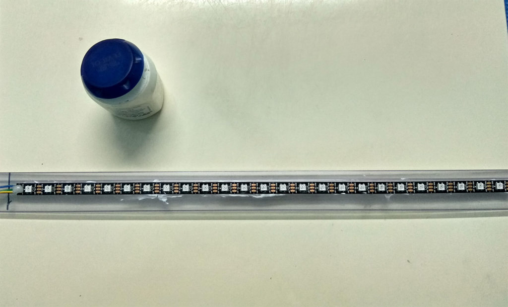
This is an RGB LED which consists of a control chip WS2812. This LED has three pins Vcc, GND and Din to control the color of this LED. Colors in this LED can be controlled via precisely timed signal. In this LED strip these individual WS2812 LED’s are chained together and can be controlled via one common timed signal from Microcontroller. In our case it is going to be our Arduino. Also do remember that this LED strip comes in 60 and 120 chained blocks. For the purpose of our project we are going to cut out 25 LED’s from the strip and use.
Remember RGB LED is a combination of Red, Green and Blue LED’s integrated in one package with each consume about 20mA of current. So a single RGB LED will consume about 60mA. So a 60 LED’s will consume about 1500mA, so you must use a power source that is capable of delivering current more than this. Check out this link to know more about these “WS2812 RGB LED strip”.
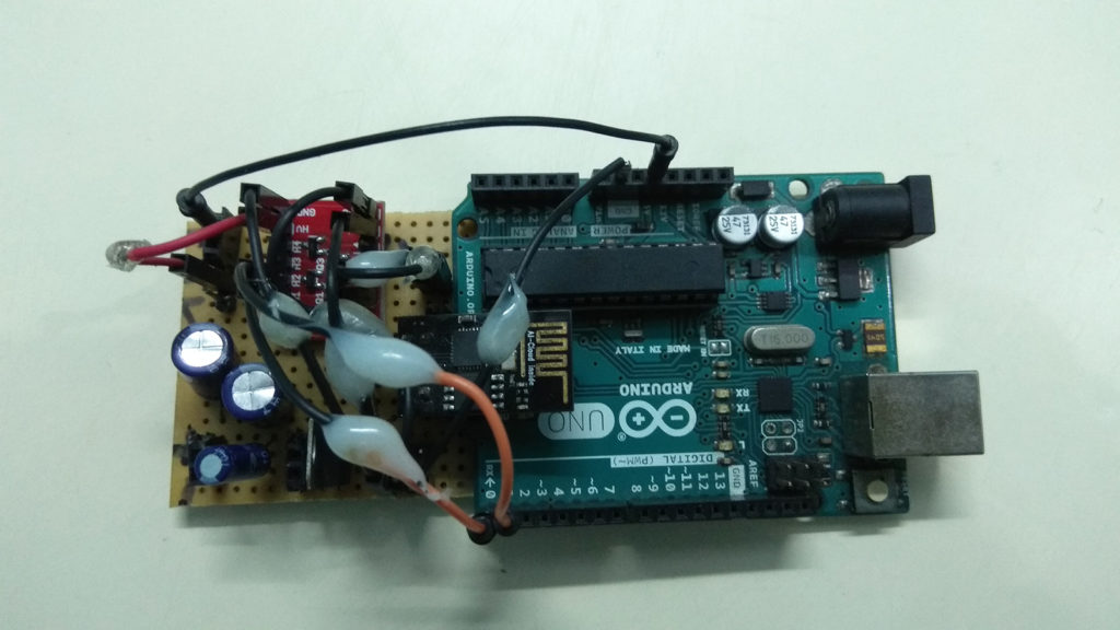
4.3 ARDUINO & ESP8266 MODULE:
Arduino will be the brain of this entire Light painting project. And I believe everyone knows that ESP8266 module is a simple WiFi developmental platform comes at the price of just $5. This ESP module will provide WiFi connectivity to Arduino and let it to connect with mobile Phone or other WiFi enabled devices.
4.4 POWERING THE WHOLE CIRCUIT:
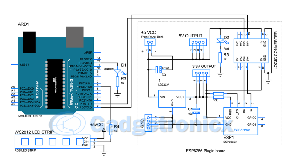
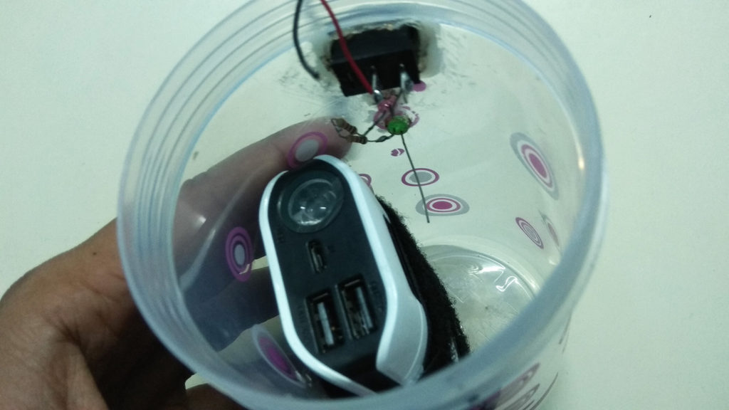
Power this entire project by using a portable power supply. I have a used a regular power bank rated ( 5.1v / 10000mah) for this purpose. This powerbank is capable of delivering current up to 2A which makes this an optimum choice for this project. In order to connect them use a cut out USB cable to power this entire circuit. The + and – from the USB cable needs to go into the + and – pins of +5Vcc as shown in the above circuit diagram. Note that you need to power up the Arduino from power bank by directly connecting it to the 5v pin of Arduino.
4.5 INDICATOR LEDS:
There are two LED’s in the circuit which acts as an indicator to the user.
Red – Indicates whether the stick is in ON/OFF state.
Green – Indicates that this system is ready to receive client request from any device connected to Arduino.
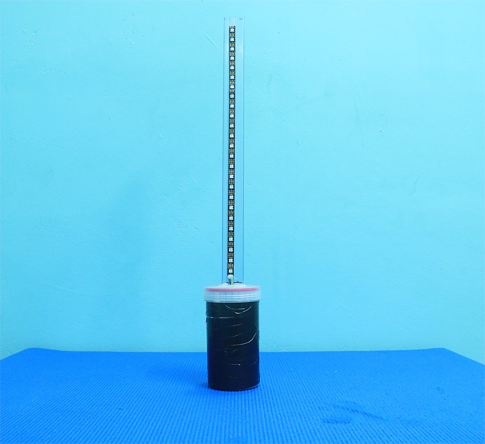
4.6 SETTING LIGHT PAINTING STICK:
I have made a video setting this whole light painting stick, watch it for more clarity.
Cut out 25 LED’s and paste it to a surface that resembles a stick
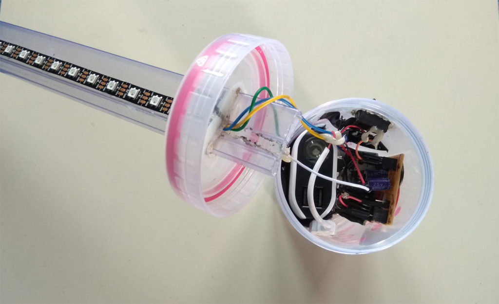
Power bank , Switch and Indicator LED’s in a container
Wiring up ESP8266 module and Arduino together ( follow circuit diagram )
Wiring the LED Strip , Arduino and Power bank together ( A big mess of wires )
I have explained the total project setup in the above video , take a look for step by step instructions on this project setup.
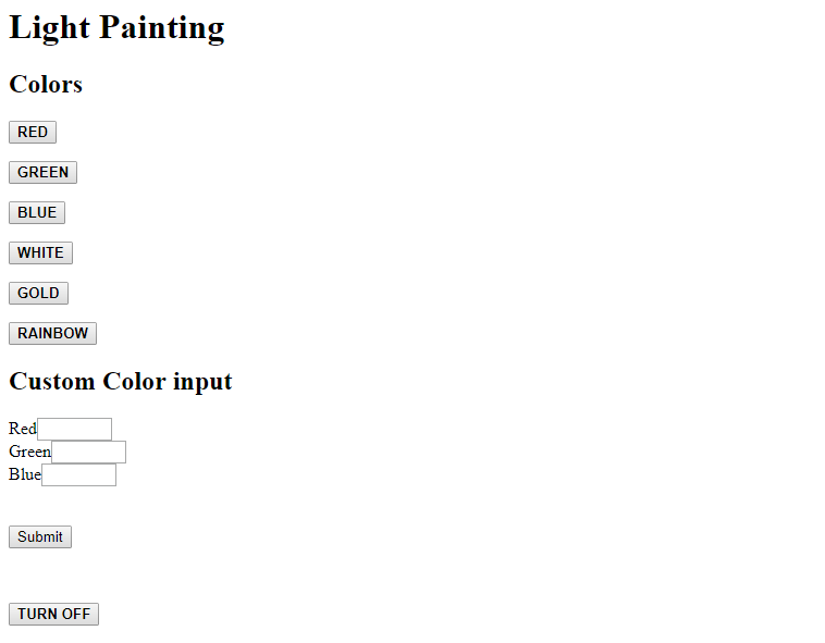
5. WEB INTERFACE:
Web interface is of great importance since it will serve as the user interface through which commands go to Arduino via ESP8266. Our web interface is pretty simple and coded in plain HTML. The buttons in this interface passes a GET command with a URL parameter with every button press. This interface consists of
WEB INPUTS
URL PARAMETERS ( LED commands )
6 buttons for standard colors
“/Red” , “/Gre”, “Blu”, “/Whi”, “/Gol”, “Rai”
Custom color input using RGB Values
“?R=255&G=255&B=255”
Turn Off the Strip
“/Off”
The value from these buttons then goes to the Arduino by means of a GET request. For example when pressed Red button a GET request with URL “/Red” will be sent to Arduino. From there Arduino will process this text and activate LED strip accordingly.
Reset the ESP8266 module by sending “AT+RST\r\n” command.
Check for the response from ESP8266 to see if the connection to our device hotspot is successful.
Once connected start feeding the “Server creation” (refer below) command sequence to ESP8266.
Monitor the response for each input commands.
All these commands should return a response of “OK\r\n”, in case of incorrect response repeat the command with incorrect response or “ERROR”.
Once all the server creation command sequence is in successfully, light up the Green LED in the pin 12 of Arduino. It will be indication for the user to provide the client request.
Force Arduino to wait for the client request from any browser lies within the LAN or Network.
Once client request is in, check for the connection ID and send the command “AT+CIPSEND….” by inserting the appropriate connection ID to it.
ESP8266 responds with a ‘>’ sign indicating its readiness in receiving the characters.
Upon receiving this send the webpage code we have saw earlier (sec 6.1) to the client browser via ESP8266 module.
Now webpage will be visible in the client browser of user, Arduino will then enter into a state of scanning indefinitely for “LED commands” from the client.
The webpage was written in a way to provide unique URL parameter for each button press, so whenever a button is pressed ESP module will pass on a GET request with that unique URL parameter.
Arduino should process this URL and provide control the RGB LED strip accordingly.
6.2 SERVER CREATION COMMANDS FOR ESP8266:
The following are the commands that to create a server in Arduino
AT
AT+CWMODE=3
AT+CIPSTA=192.168.43.253
AT+CIPMUX=1
AT+CIPSERVER=1,80
6.3 CODE:
#include <Adafruit_NeoPixel.h>
#ifdef __AVR__
  #include <avr/power.h>
#endif
#define PIN 6
Adafruit_NeoPixel strip = Adafruit_NeoPixel(25, PIN, NEO_GRB + NEO_KHZ800);
uint8_t pixel_count;

char Input_buffer[450];
boolean command_flag=false;
int i,j;
boolean stringComplete=false;
boolean request_processed=false;
boolean WiFiConnect=false;
uint8_t command_count=0;
char send_bytes[]="AT+CIPSEND= ,843\r\n";
boolean client_request=false;
boolean flag=true;
char connection_id;
uint8_t page_input_pos;
uint8_t RGB[3];

void setup() {
  strip.begin();
  strip.show();
  pinMode(12, OUTPUT);
  digitalWrite(12,LOW);
  Serial.begin(9600);
  delay(5000);
  Serial.print("AT+RST\r\n");
  delay(200);
 while(WiFiConnect==false)                             //Wait till Connecting to WiFi hotspot
  {
    serial_check();
    WiFiCheck();                                        //WiFi check subroutine
  }

  while(command_flag==false)                           //Looping for commands
  {
    command_input();
  }
  clear_buffer();                                        //Clearing the array
  while(client_request==false)                          //Waiting for any client/browser to initiate the request
  {
    serial_check();
    brow_req();                                         //sub routine to check browser request
    brow_resp();                                        //sub routine for response from Arduino
  }
  flag=false;
  digitalWrite(12,LOW);
}

void loop() {
  serial_check();
  page_input_pos=Search_webrequest();                  //Monitor webpage indefinitely
  activate();
}


void activate()
{
  if(flag==true)
  {
    if(Input_buffer[page_input_pos]=='R'&&Input_buffer[page_input_pos+1]=='e')
    drawColors(255,0,0);
    else if(Input_buffer[page_input_pos]=='G'&&Input_buffer[page_input_pos+1]=='r')
    drawColors(0,255,0);
    else if(Input_buffer[page_input_pos]=='B'&&Input_buffer[page_input_pos+1]=='l')
    drawColors(0,0,255);
    else if(Input_buffer[page_input_pos]=='W'&&Input_buffer[page_input_pos+1]=='h')
    drawColors(255,255,255);
    else if(Input_buffer[page_input_pos]=='G'&&Input_buffer[page_input_pos+1]=='o')
    drawColors(255, 190, 0);
    else if(Input_buffer[page_input_pos]=='R'&&Input_buffer[page_input_pos+1]=='a')
    rainbow();
    else if(Input_buffer[page_input_pos]=='?')
    custom_color();
    else if(Input_buffer[page_input_pos]=='O'&&Input_buffer[page_input_pos+1]=='f')
    drawColors(0,0,0);
  }
}

void drawColors(uint8_t R,uint8_t G,uint8_t B)
{
  for(pixel_count=0;pixel_count<strip.numPixels(); pixel_count++)
  strip.setPixelColor(pixel_count,R,G,B);
  strip.show();
}

void rainbow()
{
 for(pixel_count=0;pixel_count<strip.numPixels(); pixel_count++)
 {
  if(pixel_count==0||pixel_count==7||pixel_count==14||pixel_count==21)
  strip.setPixelColor(pixel_count, 148, 0, 211);
  else if(pixel_count==1||pixel_count==8||pixel_count==15||pixel_count==22)
  strip.setPixelColor(pixel_count, 75, 0, 130);
  else if(pixel_count==2||pixel_count==9||pixel_count==16||pixel_count==23)
  strip.setPixelColor(pixel_count, 0, 0, 255);
  else if(pixel_count==3||pixel_count==10||pixel_count==17||pixel_count==24)
  strip.setPixelColor(pixel_count, 0, 255,0);
  else if(pixel_count==4||pixel_count==11||pixel_count==18)
  strip.setPixelColor(pixel_count, 255, 255, 0);
  else if(pixel_count==5||pixel_count==12||pixel_count==19)
  strip.setPixelColor(pixel_count, 255, 127,0);
  else if(pixel_count==6||pixel_count==13||pixel_count==20)
  strip.setPixelColor(pixel_count, 255, 0, 0);
 }
 strip.show();
}

void custom_color()
{
  command_count=0;
  command_count=page_input_pos+1;
  for(;Input_buffer[command_count]!=' ';command_count++)
  {
    if(Input_buffer[command_count]=='R')
    RGB[0]=values('&');
    else if(Input_buffer[command_count]=='G')
    RGB[1]=values('&');
    else if(Input_buffer[command_count]=='B')
    RGB[2]=values(' ');
  }
  drawColors(RGB[0],RGB[1],RGB[2]);
  strip.show();
}

int values(char a)
{
  i=j=0;
  char numbers[3];
  i=command_count+2;
  while(Input_buffer[i]!=a)
  {
    numbers[j]=Input_buffer[i];
    i++;
    j++;
  }
  return atoi(numbers);
}

void WiFiCheck()                                        //Check whether WiFi is connected
{
  if(stringComplete==true&&Input_buffer[j-4]=='I'
  )   //Check for the status WIFI GOT IP
  {
   clear_buffer();
   WiFiConnect=true;
   delay(500);
  }
  else
  {
    clear_buffer();
    stringComplete=false;
  }
}

int Search_webrequest()                                   //repeated loop to check button inputs from Webpage
{
  if(stringComplete==true)
  {
    for(i=0;i<j-2;i++)
    {
      if(Input_buffer[i]=='G'&&Input_buffer[i+1]=='E'&&Input_buffer[i+2]=='T')
      {
        flag=true;
        return i+5;
      }
    }
  }
}

void brow_req()                                               //sub routine to monitor the browser request
{
  if(stringComplete==true&&request_processed==false)          //Checking for presence of char in input buffer and check whether the client request has already processed
   {
      if(flag==true)
      connection_id=(char)Input_buffer[0];
      send_bytes[11]=connection_id;                           //Adding connection ID to the CIPSEND command
      Serial.print(send_bytes);
      clear_buffer();
      delay(1000);
      request_processed=true;                                 //Changing the flag to true indicating that Client request is processed
   }
}

void brow_resp()                                             //Sub routine to respond to client request
{
  if(request_processed==true&&stringComplete==true)         //Checking the flag on client request process
  {
    serial_check();
    if(Input_buffer[j-2]=='>')                              //Checking for the Send data signal from ESP  module
    {
      memset(Input_buffer,'\0', sizeof(Input_buffer));
      Serial.print("<html><body><h1>Light Painting</h1><h2>Colors</h2><p><a href=\"Red\"><button><b>RED</b></button></a></br></p><p><a href=\"Gre\"><button><b>GREEN</b></button></a></br></p><p><a href=\"Blu\"><button><b>BLUE</b></button></a></br></p><p><a href=\"Whi\"><button><b>WHITE</b></button></a></br></p><p><a href=\"Gol\"><button><b>GOLD</b></button></a></br></p><p><a href=\"Rai\"><button><b>RAINBOW</b></button></a></br></p><h2>Custom Color input</h2><form method=\"GET\"><div><label for='R'>Red</label><input name='R' id='R' type=\"number\" min=\"0\" max=\"255\"></div><div><label for='G'>Green</label><input name='G' id='G' type=\"number\" min=\"0\" max=\"255\"></div><div><label for='B'>Blue</label><input name='B' id='B' type=\"number\" min=\"0\" max=\"255\"></div><br/><br/><button>Submit</button></form><br/><p><a href=\"Off\"><button><b>TURN OFF</b></button></a></p></body></html>");                                         //Sending webpage code to Client browser
      delay(2000);
      serial_check();
      //while(command_response_check==false);
      clear_buffer();
      request_processed=false;
      client_request=true;
    }
    else
    {
      clear_buffer();
      request_processed=false;                             //If request response didnt turn out successful mark the flags so that another CIPSEND command can be passed
      flag=false;
    }
  }
}

void command_input()                                      //Sub routine for commands to create server using ESP module
{
  serial_check();
  if(command_response_check(Input_buffer)==true)          //Checking the response and Tracking the counts of command to handle in case of error response from ESP
  {command_count=command_count+1;}
  else
  delay(1000);
  clear_buffer();
  switch(command_count)                                  //Enter commands sequentially in creating server
  {
    case 0: { Serial.print("AT\r\n");
              delay(500);
              break;
              }
    case 1: {
              Serial.print("AT+CWMODE=3\r\n");
              delay(1000);
              break;}
    case 2: {
              Serial.print("AT+CIPSTA=\"192.168.43.253\"\r\n");
              delay(1000);
              break;
              }
    case 3: {
              Serial.print("AT+CIPMUX=1\r\n");
              delay(1000);
              break;
            }
    case 4: {
              Serial.print("AT+CIPSERVER=1,80\r\n");
              delay(1000);
              break;
            }
    case 5: {
             command_flag=true;
             digitalWrite(12,HIGH);
             break;
            }
  }
}

void clear_buffer()                                             //Clearing buffer
{
  memset(Input_buffer, '\0', sizeof(Input_buffer));
  stringComplete=false;
}

boolean command_response_check(char *a)                         //Checking for OK Response from ESP
{
  if(a[j-4]=='O'&&a[j-3]=='K'&&a[j-2]=='\r'&&a[j-1]=='\n')
  return true;
  else
  { delay(1000);
    return false; }
}

void serial_check() {                                           //Serial char available check
  i=0;
  while (Serial.available()) {
    delay(2);
    char inChar = Serial.read();
    Input_buffer[i]=(char)inChar;
    i=i+1;
    stringComplete = true;
    j=i;
   }
}
NOTE:
This project is based on the capability of ESP8266 to auto connect with the WiFi hotspot once turned on. So the ESP8266 and your hotspot device must be paired at least once before using in this project.
The Arduino was programmed in such a way to handle only one client communication which means only one browser can request Arduino to control the LED’s
There is a wait time for creating server by the Arduino with ESP8266. The end of this wait time can be known by green LED. Once the green LED lights up you are good to initiate the client request from your browser.
You should supply the entire project with source of at least 2A in order to keep it run hassle free.
Hope you like this project, Do leave a comment if you have any feedback or queries regarding this 🙂