Liquid level indicator circuit are highly useful to monitor the level of liquids present in a tanks where access to the tanks are difficult. This circuit uses pressure sensor to sense the level of liquid in the tank. This eliminates the drawbacks such as: corrosion of the sensing electrodes, ionic conduction property of liquid etc., which were used in the primitive liquid level indicator circuits. Also the alarm in this circuit offers added advantage of alerting user to turn OFF the liquid pump or valve.
WORKING OF LIQUID LEVEL INDICATOR CIRCUIT:
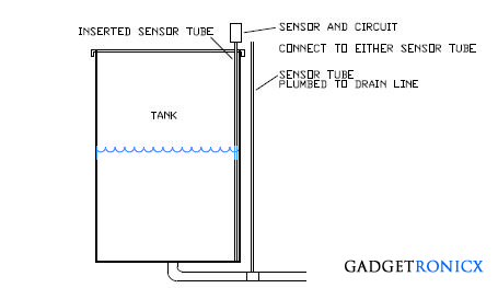
The tank is 6 to 7 feet deep and might contain oil, water, gasoline, or other liquids. A sense tube is connected to the pressure sensor port. It is attached to the bottom of the tank by either plumbing to a bottom of the tank drain line, or the sense tube is inserted to the bottom of the tank with an opening near the tank bottom. When the liquid fills the tank, the trapped air in the tube is compressed. The increase in pressure is proportional to the depth.
For water, every inch of water depth is an increase of 249.0892 Pascals of pressure. For a 7 foot deep tank, (84 inches), the resultant pressure increase in the sense tube would be 249.082 x 84 = 20,922.888 Pascals. The pressure sensor chosen is a Freescale MPXM2051G with a full scale of 7.25 PSI (50 kPa), and a full scale output of 40 mV. Since our example is 84 inches deep, the sensor output will be
40 mV * 20922.888 / 50,000 = 16.74 mV
In order to obtain the best resolution, a desired output for full is chosen to be between 4.0 and 4.5 volts. Thus, a gain of approximately
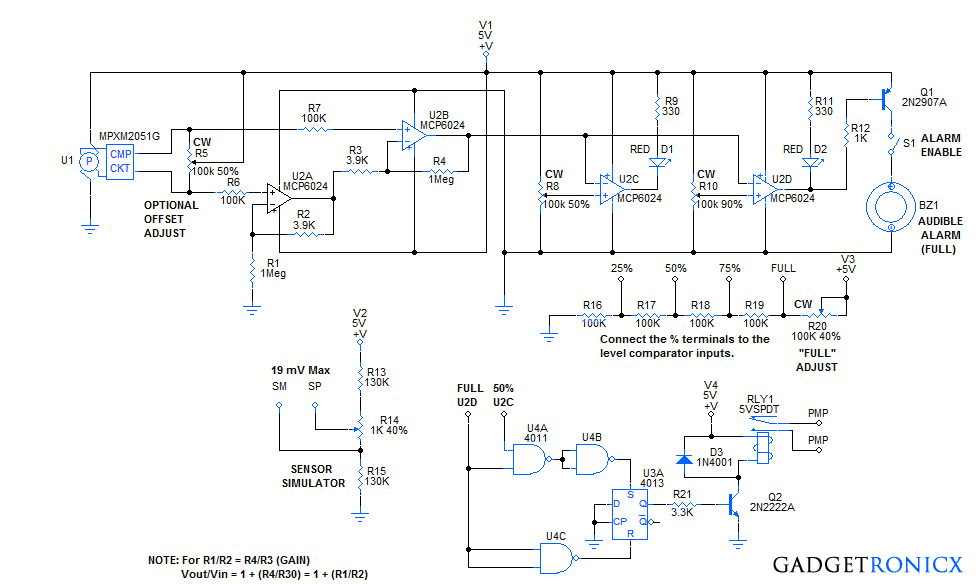
The pressure sensor is connected to Op-amp U2A and U2B via R6, and R7 respectively. U2A and U2B are used as differential input amplifier referenced to ground. This means that if the pressure sensor +/- outputs are equal, (when pressure is zero), then the output of U2B will be zero.
As the sensor pressure rises, the differential output increases. In our example, when the pressure reaches 20,922.88 Pa, or 20.923 KPa, then the output will be 16.74 mV. The GAIN of the differential amplifier, when R1/R2 = R4/R3 is GAIN = Vo/Vin = [1 + (R4/R3)] = [1 + (R1/R2)]. Applying this formula to the needed GAIN of about 250. The schematic values obtained were R1, R4 = 1 Meg, and R2, R3 = 3.9K ohms. Plugging those values into the GAIN formula yields,
Thus, at full scale, the sensor output for a depth of 84 inches = .01674 * 257.41 = 4.31 volts.
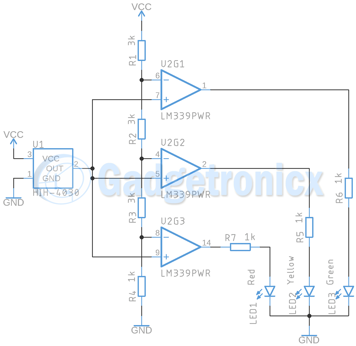
U2C and U2D serve as comparators which compare the output of U2B to an adjustable reference provided by R8 and R10. If more levels are desired, U2A and U2B can be in a MCP6022 dual RRIO op-amp and an additional MCP6024 quad RRIO op-amp can be used as a four level comparator. In the schematic, The tank can be filled to a desired level and the reference pot R8 adjusted so the LED, D1 just turns ON. The tank can then be filled to full level and reference pot R10 adjusted so LED, D2 just turns ON. R12, Q1 and BZ1 form an audible alarm that can be added if desired to indicate the full level. Adding a switch to turn OFF the alarm may be desired.
If the dual – quad op-amp approach is used, the MCP6024 quad op-amp can be connected to the resistor ladder shown. All of the -inputs of the op-amps are connected to the output of U2B. The +inputs are connected to the 25%, 50%, 75%, and FULL nodes of the resistive ladder. R20 serves as an adjustment for the FULL tank level. Then each LED will represent a one fourth of FULL value. This only works for a vertical walled tank. If you use a cylinder on it’s side, then the tank should be filled in fourths, a pot used to just turn ON the appropriate LED. In other words. Use a pot to adjust each individual LED level threshold.
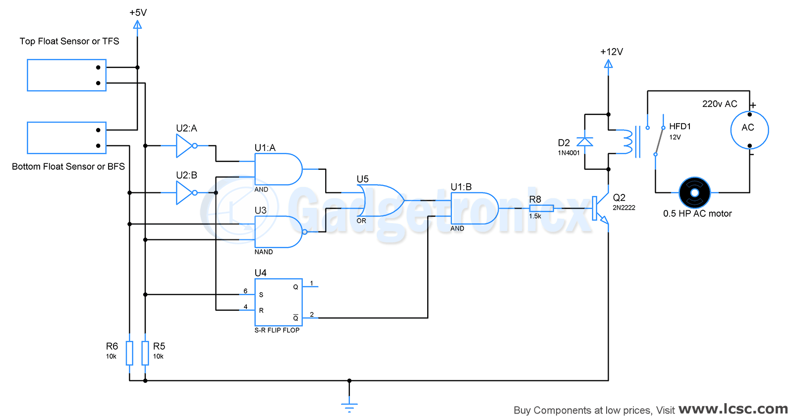
One more thing could be added to automate the tank filling. If an R-S latch, (RESET-SET), was connected so that it was set when the tank was below one of the lower levels, say 50%, and then reset when it reached 100%, the latch output could drive a relay to turn ON and OFF a fill pump, or OPEN and CLOSE a solenoid fill valve. This would automate the tank filling procedure and eliminates the need of an alarm.
I included a circuit to simulate the sensor in order to test the circuit. It divides the 5 volt supply into a middle reference (Vsupp/2) and differential adjustment from 0 to 19 mV. I hope everyone finds this circuit useful for a universal liquid level indicator.
Finally, another thought is to take the output of U2B and perform an A/D conversion with a PIC microcontroller. And then light a given LED whenever the A/D reading is above a defined level in the program. This way, you could have as many levels as desired. Another idea would be to do some simple integer math in the PIC and indicate the level on an LCD display as a percentage. The advantage would be higher resolution of the tanks fill level.


How intrinsically safe is this circuit if used with a flammable liquid with a low flash point such as gasoline? Thanks
Tom, I’m not sure if you are referring to the Ionic Liquid Level detector or the Pressure Liquid level detector. One uses a small
AC current and only works with water and ionic liquids. The pressure type detector works with all liquids and would be safe even with gasoline. The pressure tube can be run above or away from the tank so that there are no electrical components even near the gasoline. The pressure version is a bit more costly, but absolutely needed if your controlling the level of any flammable liquid. Regards, Ron H.