
Humidity is the measurement of water content that is present in gaseous form in air. It has applications in Weather forecasting, Air conditioning, Industrial spaces, Ventilation etc. You might have seen many of these measurement systems which uses Microcontroller to make the measurement and indication. Here in this circuit we are going to just use Opamp’s and sensor to make a simple Indicator that indicates the level of humidity using three LED’s.
Part List:
- Battery 5VDC
- LEDs ( Red, Green and Yellow )
- Resistor 3k – 3 nos
- 1K Resistor – 4nos
- Integrated Humidity Sensor HIH-4030
- Quad Opamp chip LM339
Working of Humidity sensor Circuit:
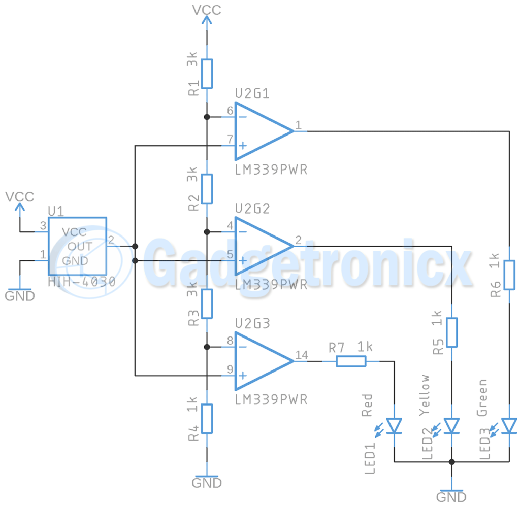
In this circuit we are using an Integrated Humidity Sensor HIH-4030, three Op-Amps to sense the output from the sensor and switches the indicator LED’s based on its intensity. For showing the results we have 3 LED’s. The sensor is very simple and has 3 pins. Apart from the 5V DC supply and GND pin, it has an analog Voltage output pin. The output in this Analog out pin depends on the Humidity of the environment. Therefore analog voltage output from the sensor increases with the relative humidity present in the atmosphere.
The output from this Sensor feeds to all the Inverting input of Opamp. A voltage divider using R1, R2, R3 and R4 is made to feed reference voltage to the Opamp’s for the purpose of comparison to the Comparator. The inverting input of U2G3 is fed with 0.5v from the voltage divider set up. So when output of the sensor rises above 0.5V the Op-Amp will detect it and will turn on the Red LED. This indicates the presence of 10% relative humidity in the atmosphere. Inverting pin of U2G2 is fed with 2v from Voltage divider. When the sensor output exceeds 2v it activates the yellow LED indicating 45% relative humidity presence in the atmosphere. Inverting pin of U2G1 is fed with 3.5v and when the sensor output exceeds this it activates the Green LED indicating 75% presence of relative humidity in the atmosphere.
You can swap the places of LED’s to your desire. Also you can also increase the number of Comparators used and add more indicator LED’s for wider relative humidity indications in the output. We believe this circuit would have been useful to you. Kindly checkout our Electronics Circuit library page for wide variety of circuits. Leave your queries below in the comments section.


I have designed this project on Proteus, but my LEDS are not glowing.
Can you tell me that what is the issue?
Is it fine if I used a resistive humidity sensor instead of capacitive humidity sensor ??
Thank you
Yes you can use a resistive humidity sensor. But these sensors change their resistance as humidity changes so you have to use a series resistor with it and build a voltage divider. The voltage output from this set up can be fed to comparator inputs.
Can you draw it for me? I’ll appreciate that
Thank you
Here is a a voltage divider using resistive humidity sensor
So the right part is same, I just have to replace the left part (sensor, GND and Vcc) ?
But it works with same principle, is not ?
The submission of project tonight, so please reply
Yes the comparator remains the same. But you are going to replace the sensor in the circuit with the voltage divider and resistive humidity sensor I have given in the diagram