
Heat sensor circuit diagram can be found plenty online and each of them serves their purpose differently. Here is one of heat senor which serves as a warning equipment which indicates whenever the temperature exceeds the preset level. This circuit diagram uses simple thermistor to sense the heat of the surroundings and then use LED and buzzer as an activator.
WORKING OF HEAT SENSOR CIRCUIT DIAGRAM:
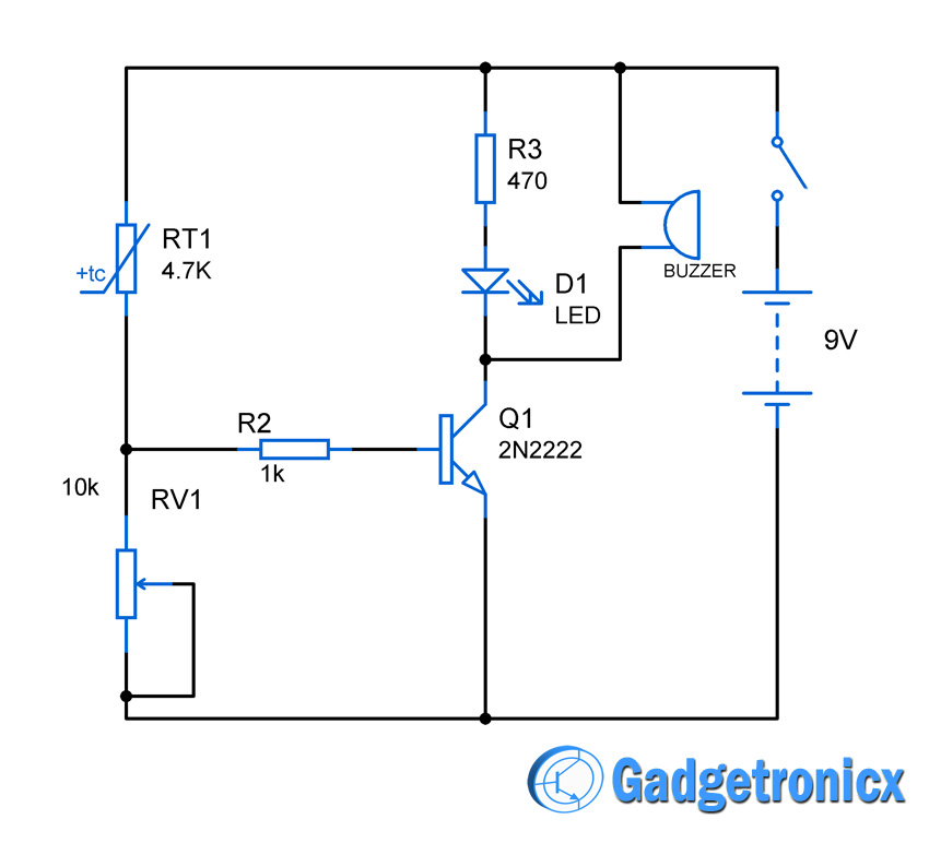
Thermistor was employed as a heat sensor in the above circuit. The resistance of the thermistor drops whenever there is a rise in temperature, hooks with a POT we can build a simple voltage divider which forms the heat sensing part of our circuit.
The output voltage from the divider is then fed to the base of the transistor Q1 which turns on the indicating elements LED and Buzzer when the current temperature exceeds the preset voltage. A switch was used to turn on the circuit.
The preset temperature can be set by changing the resistance POT resistance RV1. It should be set in such a way that the base of the transistor is provided with enough voltage whenever the temperature exceeds the preset temperature. So that the indicating elements LED and buzzer can be turned on by the transistor.


