Wastage of water is a common issue among households. There are industrial grade water level detectors which monitor the water level in tanks and activate or deactivate the motor based on water level. However those industrial equipment tend to be expensive for household usage. For this purpose I have designed an Automatic water pump controller circuit that can monitor water level in your tank and when water reaches maximum threshold of the tank this circuit turns motor off. Similarly when water level goes below say 10% of total tank capacity, this circuit turns the motor ON enabling water to fill the tank. The cycle repeats thereby automating and controlling water flow to the tank.
MAGNETIC FLOAT SENSOR:
This project uses a magnetic float sensor in it. This float sensor is a simple switch which closes when water reaches its level. This moves the magnet inside and attracts the metal contact inside it and therefore closing the switch. This therefore allows current to flow through the sensor . This way the water level can be sensed.
This circuit uses two of these water level sensors. Let’s name them Top Float sensor or TFS and Bottom Float sensor or BFS. A high signal from TFS indicates that water has reached maximum capacity of the tank whereas low signal from BFS indicates that water has gone below 10% of its capacity.
To completely automate the water pumping process we need to adhere the following conditions
Water is above the maximum capacity and motor needs to be turned off. At this instant both TFS and BFS will give high state as output.
Water starts to get consumed and its level goes below TFS sensor but above BFS sensor. At this point the motor should still be in off state.
Further water usage forces the water level to go further below BFS sensor and at this point BFS sensor should give high output and motor needs to be turned ON.
Now that the motor is ON water starts filling the tank and after some time water level will raise above BFS sensor. At this point the motor should continue to fill the tank until water level reaches the TFS sensor. Then the system cycles back to first condition. The cycle repeats indefinitely automating the pump mechanism based on water level in the tank.
The above conditions can be coded into below truth table
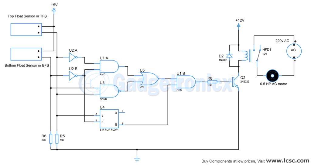
Let’s analyse this circuit from motor driver and water pump. It comprises of Resistor R8, Q2, D2 and Relay. Output from U1:B drives this motor driver, high output from it will activate the relay and this in turn activate the water pump connected to it. Low output from U1:B will result in turning off the relay, therefore water pump will be deactivated as well. Let’s do some math and fix the component values.
Water pump we have used here in the circuit operates at 220v AC and rated 0.5HP which equate to 372.85 Watts. The current consumed by this water pump will be
I = 372.85 / 220 = 1.7A
We need a relay that can handle this current at 220v. I found a relay HFD7012-M which suits this purpose, it can handle current up to 2A. The coil resistance of this relay is 450 ohm and is rated 12v. Therefore we need to supply a current of
I = 12 / 450 = 27mA
to activate the relay.
The transistor we have chosen is 2N2222A which has a gain hfe of 10 in saturation region. So to activate the relay using this we need a collector current of 27mA and base current should be 2.7mA. We use this to fix base resistor for our transistor
Rb = ( 5 – 1.3 ) / 2.7 x 10-3 = 1.5k ( approximately )
Now the motor driver and water pump part of this circuit is sorted out, let’s proceed to the controlling part of this circuit.
CONTROL SECTION:
The working of this circuit starts from Magnetic level sensors TFS and BFS. The TFS should be installed at top of tank to detect water level when maximum capacity is reached. Meanwhile BFS goes to the bottom of tank in a way it detect when water level falls below 10% of its capacity due to consumption. Both of these sensors act like a switch and closes the electrical connection and conducts current when water reaches its level. One end of this sensor goes to Vcc whereas other end feeds input to next stage. This terminal is pulled down using a resistor otherwise it will be in a floating state. Let’s analyse the above circuit based on the conditions plotted in our truth table.
Note: The circuit should be turned ON only after filling up the tank to its maximum level or in a level where both the sensors will be active and gives high output. This ensures that our circuit follow the right sequence and works correctly.
1) TL = BL = 1 OR MAX WATER LEVEL:
When the circuit is turned ON water will be at its max level and TL and BL will give logic 1. At this point the output of U5 will be low. Input to Set pin will be 1 and Reset pin will be 0 for SR Flip Flop. Therefore Flip Flop gives low output at Q’. As a result output of U1:B will be low therefore turning the water pump off.
2) TL = 0, BL = 1 OR HALF WATER LEVEL AFTER CONSUMPTION:
The water will be consumed and level in the tank drops down. This results in deactivating the TFS sensor or TFS = 0 keeping only the BFS active or BFS =1. In this case output of U5 will be high. Set pin and Reset pin of SR flip flop will be 0. Therefore output logic from Q’ will be of no change and water pump will still be in off state.
3) TL = 0, BL = 0 OR WATER LEVEL GOES BELOW 10% AFTER CONSUMPTION:
Further consumption of water will drop the water level further down and when it goes below 10% of tank capacity both TFS and BFS will give logic 0 as output. At this instant output from U5 will be high. The sensors will feed 0 to set pin and 1 to reset pin of SR Flip Flop. This forces high output at Q’ pin of Flip Flop. This altogether forces output of U1:B high driving the motor driver and turn the water pump ON. Therefore water will begin to refill the tank.
4) TL = 0, BL = 1 OR WATER LEVEL INCREASES ABOVE 10% AFTER PUMPING OF WATER:
As water starts filling in the tank BFS will get activated first resulting its output Logic 1 while TFS output will be still logic 0. At this point output of U5 will be high. Both Set and Reset pin of SR Flip Flop will be at logic 0. Output from output pin Q’ will therefore undergo no change from previous state which is high output. High input from U5 and Q’ will give high output from U1:B as well. This goes to the motor driver and keep the water pump ON. And water will still continue to get refilled in the tank.
The above four conditions repeats itself thus automating the activation and deactivation of water pump. The most important thing when using this circuit is we need to power this ON after fixing TFS and BFS at appropriate levels and have the tank filled with water completely.
This project will greatly save water and automate the process of refilling your water tank everyday. There are few things that you need to keep in mind when implementing this project.
NOTE:
Different motors have different HP rating, you may need to alter the components such as base resistor R8, Transistor Q2 and Relay based on your motor ratings.
You have to perform the calculations under Motor driver section with your motor ratings and use it in the circuit you build.
Hope this Project was useful to you. Do build them and let us know about it. Check out other Electronic projects in our website here. If you have any queries or feedback, do post them in the comments section below. Happy project building 🙂
It is verify import for water pump automatic controlling. In this blog perfectly describe step by step automatic water pump controller process. This is help for new user of water pump. Thank for great idea sharing with us.


 Microcontroller")
Is there any video tutorial for this?
It is verify import for water pump automatic controlling. In this blog perfectly describe step by step automatic water pump controller process. This is help for new user of water pump. Thank for great idea sharing with us.
how can i search for the magnetic float sensor?
There are tons of online vendors you could buy from.