SMT ( Surface Mount Technology ) or SMD ( Surface mount devices ) has become popular due to several reasons. First of all its cost efficient and requires less space as compared to Through Hole Components. As the name suggests SMD is mounted directly on the surface of either top or bottom side of PCB, while THT components are inserted into PCB. SMD components saves a lot of mounting areas in the PCB. Also the SMD components are relatively smaller in size which reduces the overall dimension and complexity of circuit board. Many hobbyists and makers consider SMD soldering to be daunting but it’s far from reality. All it needs is right tool and some practice.
In this article we are going to see the techniques involved in SMD soldering and things you should know about it. We only focused on the techniques that are mainly used by hobbyist makers and not factories Before getting started with soldering SMD components you should know a few things about SMD components itself.
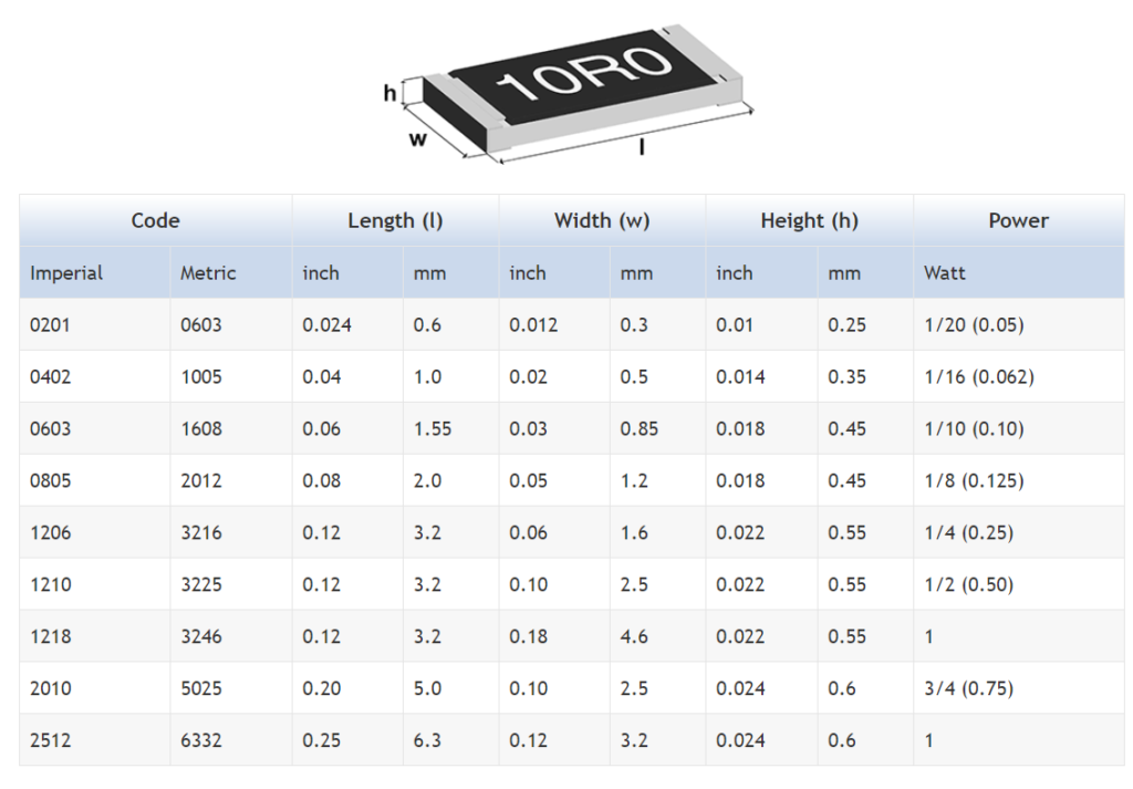
Package Size :
Size is a very impotent factor when it comes to SMD components. Passive components like resistors, capacitors, diodes come in various package sizes such as 1206, 0805, 0603 etc. These numbers denote the actual size of that component. Always keep that in mind while designing the PCB for your project and buying the SMD version of that component. Because it is very frustrating when you bought a full pack of 1206 SMD resistor and later turns out that footprints in the PCB are all 0603!
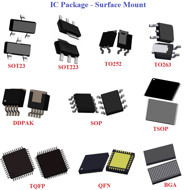
Other components such as Transistors and ICs also have different packages. For general purpose SMD transistors, the SOT23 (Small Outline Transistor) SMT package is mostly used. The SOT23 generally has three terminals of transistor, two of them on one side and third pin is on other side. But it can have more pins depending on the nature of IC, it is being used for. For example small integrated circuits such as an operational amplifier, etc.
SMD Integrated Circuit comes in a variety of packages as you can see above. And each of them has particular area where it is most suitable. However SOP (Small Outline Package) and QFP (Quad flat pack) are generally used by the hobbyist and makers due to its easier handling and assembly. And with that being said let’s talk about how to solder these components.
Soldering SMD components might seem difficult at first, but it’s not that hard once you know the proper technique and have the right tool to do it. There exist different techniques for SMD soldering. Out of which these three types are most commonly used by the makers.
1. Hand Soldering
2. Hot Air Soldering
3. Hot Plate Soldering
Hand Soldering :
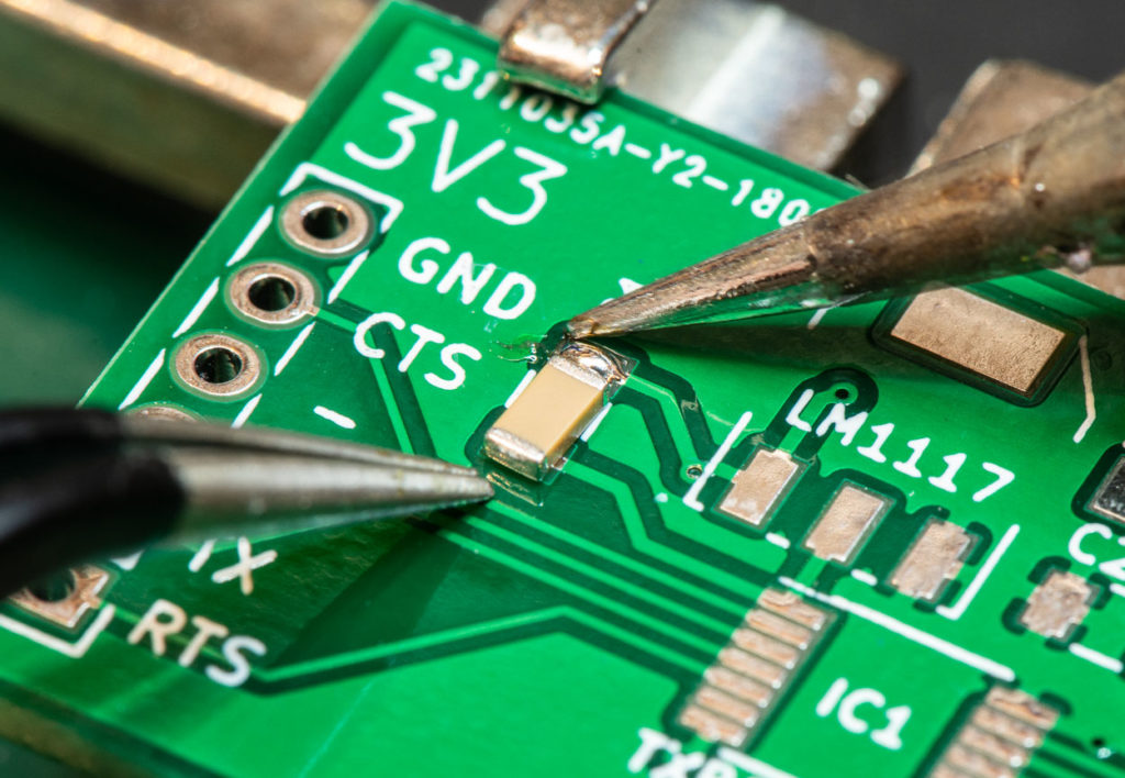
Hand Soldering is the most traditional way we solder the SMD components. This is done using a Soldering gun. This might be difficult at the beginning but after a few days of practice you will get used to it. You will need a very fine tip soldering iron (preferably one with temperature control) to get better precision, a lot of flux and some patience.
Generally you can solder 1206 to 0603 packages by hand without much of a problem. But if you go smaller than that, then you may need a microscope or a magnifying glass because these are so tiny. Let’s see step by step on how to solder SMD components.
First add some flux to PCB footprints. It will help to keep the solder in place.
Proceed to add a little bit of solder in one pad.
Use a tweezer to grab the SMT component and align it with the PCB footprint
Finally push the component gently to the pad while heating it by the soldering iron
For IC’s and components with more than two to three pins solder the diagonal pins first, this will help you keep the IC in place
Solder rest of the pins afterwards
Hot air Soldering :
This soldering method is bit easier than using a Soldering iron. In this process instead of soldering iron, Hot Air station and Solder paste are used to mount the components. Here is step by step instructions to perform Hot air soldering.
First soldering paste is applied to the footprints.
A dedicated stencil makes this process easier but if you don’t have any then use a solder paste pen or injection to apply on pads.
Place all the components one by one. Then set the temperature of the hot air station to around 300-350 degree C and expose the board to hot air.
When paste starts melting it will automatically suck the component into its position.
One important thing to remember is that do overheat any component as it may damage it permanently.
Check datasheet of the component in order to understand its temperature profile. In case of a LED apply heat from the underneath of the PCB.
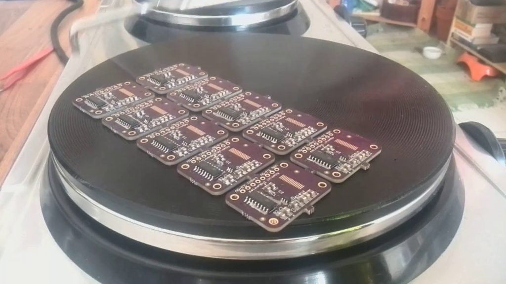
Hot Plate Soldering :
This process is similar to the Hot air soldering but instead of manually heating the components one by one here, a heated bed is used to heat the entire PCB board enabling it to solder all the components at once.
You can buy a commercial hot plate station available in the market or make one by yourself using a simple household clothing iron. This is a very fast and clean method compared to the other two mentioned above. Only downside is that you can solder only one side of PCB using this method, that’s a bummer!
Tools :
Appropriate tools are always necessary to make a clean soldering. Also it will make our life easier.
Tweezer :
A tweezer is very essential while soldering Surface Mount Components. Because you just can not grab a SMD resistor or capacitor or any components with your bare hands. Also it will help you to align the components properly. Besides using tweezers while handling components will eliminate the risk of part damage due to static electricity.
Flux :
Good amount of flux always makes the soldering neat and well finished. Flux removes oxidation in the board and prevents oxidation on the solder joints and provides better adhesion. Liquid flux is used before applying Solder paste on the PCB. Flux comes in different forms like Paste, Pen and Syringes. Flux pen is mostly used when comes to SMD soldering process.
Stencil :
A PCB stencil is nothing but a stainless sheet which has component footprint cut out of it. Stencils are used in a way it is aligned over the board to match the footprints and solder paste can be applied to the solder pads with ease. A PCB stencil is not required but it certainly comes handy while there are too many footprints on the PCB or you need to mass produce the same board.
Soldering Stand :
A soldering stand helps to hold the PCB in position while soldering. There are several variants of such stands in the market. Some of them come with a magnifying glass built in, which is well suited when comes to SMD soldering. Also buy stand which is sturdy and less prone to move while soldering.
Desoldering braids/ Pump:
These can come in really handy if you need to do some rework on your PCB and this will make the rework a breeze if you know how to use them. Both wick and pump work in the same way while wick removes the solder lead by scrapping of the joints however pump suck them out with air pump mechanism.
Hot air rework station:
This station will come into picture if you choose to solder your S.MD components by Hot air method. This equipment make the solder joint by blowing hot air to the joint. The temperature of output air ranges from 100 to 300 usually and may vary from one model to another.
Finally it’s important to practice soldering SMD components to get the knack of it. You can choose the soldering method that suits your time, budget and quality requirement.
Hope this article has given some insights and useful tips for soldering SMD components. If you feel that we have left out any important aspect of SMD soldering, drop a comment below. Also please leave your queries, feedback about this article in the comment box below. We have more resources of PCB designing and Assembly here, check them out.

 Hand Soldering is the most traditional way we solder the SMD components. This is done using a Soldering gun. This might be difficult at the beginning but after a few days of practice you will get used to it. You will need a very fine tip soldering iron (preferably one with temperature control) to get better precision, a lot of flux and some patience.
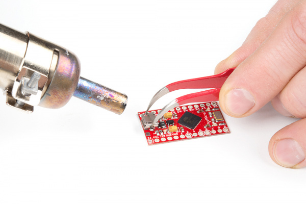 This soldering method is bit easier than using a Soldering iron. In this process instead of soldering iron, Hot Air station and Solder paste are used to mount the components. Here is step by step instructions to perform Hot air soldering.