Joysticks, who doesn’t love it! We thought to incorporate the fun of Joystick into electronics and designed a circuit that control servo motor using Joystick controller. Servo motors has robust applications and mainly known for their precise control over distance and angle. With the help of accurate signal at its data pin of servo, we can adjust the rotating angle and speed with high accuracy. This data signal is usually a PWM (Pulse Width Modulation) signal. Usually we use a microcontroller to generate PWM signal or controlling servos but we will try a different approach.
For better understanding of this circuit check out Servo motor driver using 555 Timer IC. We will use the same concept to control the servo but here we use Joystick controller in place of MCU’s or chips.
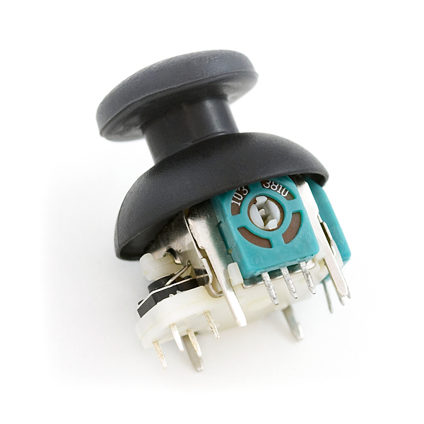
JOYSTICK:
Image courtesy: Sparkfun
The Joystick module we have used here uses two independent linear potentiometer for X and Y axis. The potentiometer were placed in such a way their resistance value changes when the Joystick moves in horizontal or vertical direction. As mentioned earlier one potentiometer is connected to X axis and one with Y axis. This potentiometer value reveals the position of joystick in corresponding vertical / Y and X/ horizontal direction. The potentiometer position and voltage level from POT were fed into 555 timer IC and in turn generates the PWM signal to drive the servo motors.
556 TIMER IC :
We know that we can generate PWM signal using a 555 timer IC in Astable Multivibrator mode. Now if we need to control two Servos we need two 555 timers or we can use 556 Timer IC which is a dual 555 timer IC, so it has two two timer modules in one 14 pin package. Only the VCC and GND pin is common.
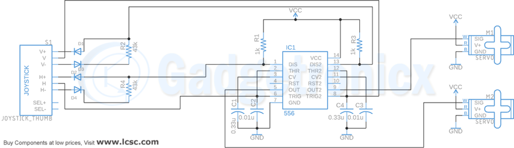
In our circuit moving the joystick in horizontal or X axis will control Servo motor 1 and moving it in vertical or Y axis will control Servo motor 2 ( forward and reverse direction ). To simply put each servos will be controlled using individual POT values of Joystick module and individual timer chip. Along with that we need a couple of passive components such as resistors, capacitors and diodes.
IC 556 has two 555 timer units and two Astable multivibrator units are built around these two timer units. Let’s consider Astable multivibrator built around Timer 1 module of 556 IC chip. Here in this Astable multivibrator Resistor R1 along with Potentiometer in the Joystick module and Capacitor C1 acts as timing element for Astable multivibrator to generate our PWM signals.
The H pin of the joystick feeds the voltage altered by joystick moving in horizontal or X axis. This voltage goes to the Trigger pin 6 of IC 556. Therefore whenever you move the joystick in X axis this voltage will be altered and as a result the output signal pulse width varies. This generates the required PWM signal to drive the servo motor M2. The rotating angle of the servo depends upon the width of the our output pulse.
The exact thing happens with second Astable multivibrator that’s built around Timer 2 module of IC 556. Here the trigger pin is connected to V pin of Joystick module. The voltage value in this V pin will vary when you move the joystick in Vertical or Y axis. By this way it influences the PWM output from 9th pin of IC 556. This in turn rotates the servo motor M1 in desired angle.
We also need a 100nf capacitor C2 and C3 at the control voltage pins of IC 556 to eliminate noise. Typically servos worked on 4.5v – 6v so you can use a 5v power supply for powering the motor as well as the Circuit.
PART LIST:
Capacitor 0.33u ( 2 ), 0.01u ( 2 )
Diode 1N4148 ( 4 )
IC 556
Servo Motor ( 2)
Resistor 1k ( 2 )
Thumb Joystick
Hope this circuit was new and fun to you. Do try this circuit out and share your feed back or post if you have any questions in the comment box below. We are happy to help with it. Happy DIY 🙂