
Single transistor FM transmitter circuits are quite famous since it is easy to build and cost less. These transmitter circuits may not provide long range like circuits that use dedicated FM chips but it will get the job done. This article shows you a simple FM transmitter circuit diagram and explains in detail about its working and part selection method. This radio Transmitter transmits signal up to a range of 20m-30m. The circuit is powered by 3.3V battery and includes a NPN transistor, a LC tank circuit and an antenna.
Related circuit: FM spy bug circuit using transistor
Components Required
- Antenna
- Transistor 2N3904
- Inductor
- Variable Capacitor
- Resistors and capacitors
- Electret microphone
- Battery(3.3 V)
Working of FM Transmitter
In a FM transmitter circuit , weak audio signals(message signals) are transmitted with the help of a carrier signal which is possess high power. This powerful carrier signal is then modulated or coded using the actual audio signal by a process known as modulation ( explained here ). This modulated signal possess enough power to be radiated aka transmitted through antenna. This in turn received by FM receivers that are tuned to pick up signal of transmitted frequency and demodulated to recover the original audio signal.
FM signal is obtained by varying the carrier frequency and it has two frequencies which are message signal frequency and carrier signal frequency by that way message signal is transmitted and at receiver original signal will be obtained.
FM Transmitter Circuit
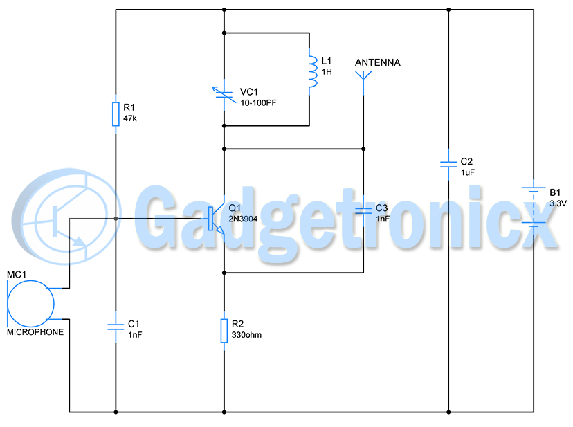
The circuit shows the FM Transmitter with power supply of 3.3 V. The microphone is used to receive the audio signals which is powered and biased using the resistor and internally the microphone has a capacitive plates which develop voltage across it when audio waves hit its diaphragm membrane. When user speaks to the mic the voltage varies at the divider junction producing a audio signal. Capacitor C1 removes the DC noise from the audio signal and feed it to the base of transistor Q1.
The transistor follows the incoming audio signal. The important thing here is the LC tank circuit. This tank circuit basically produces a signal of fixed frequency. When current flows through inductor it resists the current flow whereas capacitor charges to the level of Vcc. When capacitor reaches Vcc, it stops charging and forces current through the inductor. The electric charge built up across Capacitor depletes while pushing the current through inductor. This charges the inductor the charge is exhibited by means of magnetic field around indictor.
Now there will be no charge in the Capacitor and Inductor starts discharging pushing the current to Capacitor while charging it in the opposite direction. This cycle continues and a signal of fixed frequency will be generated across the tank circuit. This is given by the formula
fo =1/2π√LC
for L=1 H and C=1 pF
fo=1/2π√1 x 1 x 10-12
=159.15 K Hz
This signal of fixed frequency will be modulated by using the incoming audio signal by the transistor. The modulated signal is then radiated to the antenna. This way it transmits the audio signal and reaches any receiver that is within 30 meters.
Note:
- The capacitance of capacitor VC1 can be changed using the trimmer. This will alter the frequency of carrier signal.
- Increasing the supply voltage to the circuit will increase the radiating power and therefore increases the range.


Site trés intéréssant. Merci pour ce travail