
A servo motor is an electronic device which allows precision control over angular direction. When it comes to moving or rotating objects in a precise angle then a servo motor is the best choice for such applications. It consists of a simple DC motor coupled with a position feedback system to determine the motor position. We will use a continuous rotation servo that can rotate 360º. It’s a common practice to use Microcontrollers to control servo motors. However in this Servo motor control circuit we are about to use timer chip IC 555 to control it’s direction.
SERVO MOTOR:
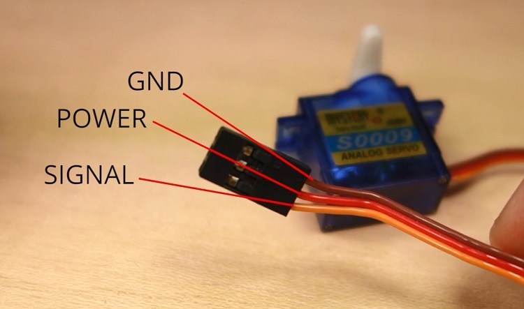
All Servos needs 3 pins to operate VCC, GND and SIG pin. The SIG pin requires a PWM (Pulse Width Modulation) signal to adjust the angle of rotation for the Servo.
SERVO MOTOR CONTROL CIRCUIT:
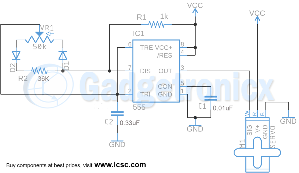
We use the very popular 555 timer IC in astable multivibrator configuration to be able to generate the desired pulses. The 555 timer IC is very cheap as compared to a microcontroller and it does not require any programming. Here we are modifying the Astable multivibrator to alter the width of the output pulse generated by IC 555.
PWM INPUT SIGNAL:
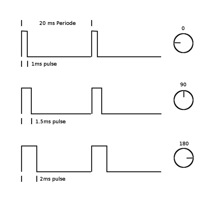
First let’s talk about the signal we need. So as we said earlier it’s a PWM signal of 50Hz. So the time period will be 1/50 sec or 20ms. The angle of the servo varies according to the ON time period of the signal and we will set that using potentiometer.
 WORKING OF CIRCUIT:
We all must be familiar with the Astable configuration of the 555 timer. We need to adjust the duty cycle in such a way that it can produce control pulses of 20ms time period. But at the same time we need to modify the width of the output pulse. So we are introducing a POT VR1 , Diode D1, D2 and Resistor R2 for this purpose. So what happens here is that when the circuit is powered ON, the capacitor gets charged via Resistor R1 and the charging current flows through the POT VR1 and proceed to charge C2 since Diode D1 allows passage for current to pass through meanwhile Diode D2 blocks this current preventing it from flowing through R2. During charging of Capacitor C2 the output of 555 will be of high state.
TON TIME:
The timing of this high state is determined by the formula
TON = 0.693 x ( R1 + VR1 ) C2
Let’s say the VR1 is adjusted to 9K, substituting the value in the above formula will yield
TON = 0.693 x ( 1K + 8K ) 0.33uF
= 0.693 ( 9k ) 0.33uF
= 2ms
So when you adjust the POT to 8K the ON time of the pulse will be close to 2ms and therefore the Servo will rotate about 180.
TOFF TIME:
At the point when 2ms of ON time is elapsed output of IC 555 will switch to low state. In this state the capacitor starts discharging through POT VR1 and into the diode D2 to the pin 7 of IC 555. To determine the TOFF time we can use the values of POT VR1 and R2. POT VR1 will exhibit 42K to discharging current since it was in a position to exhibit 8K for charging current ( 50K – 8K = 42K ).
TOFF = 0.693 x ( R2 + VR1 ) C2
= 0.693 x ( 36K + 42K ) 0.33uF
= 0.693 x ( 78K ) 0.33uF = 17.8 ms
The above result shows the OFF time will be of 18ms approximately.
SUMMING UP ON AND OFF TIME:
If you sum up the ON and OFF time of the above circuit when using these components with the circuit it will result in a pulse width of time period of 20ms which is the acceptable pulse time period to control Servo motors. And since the ON time is of 2ms servo motors will rotate 180.
So in this circuit when you adjust VR1 the ON time and OFF time will vary but the total time period will remain the same 20ms. As a result controlling the angle of rotation of Servo motor without a problem using the Potentiometer VR1.
NOTE:
- Most of the servos usually works in between 4.5v to 6v.


