Now a days there is a trend of using microcontrollers in projects where it is not necessary. This increases the cost of project and increases the complexity since it includes programming. Similarly most designers always go for Microcontrollers when they want to drive a stepper motor. This is not necessary we can make a simple circuit for this application wit some chips and discrete components. In this article we will explain this Non – MCU approach of building a stepper motor driver circuit. If you are new to Stepper motors I suggest you to read this tutorial where I have explained about its Working, construction, types and driving methods.
STEPPER MOTOR DRIVER CIRCUIT:
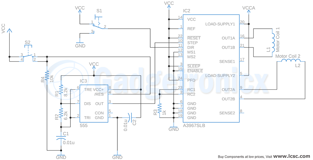
This driver circuit is intended to control bipolar stepper motor using microstepping method. This is where step current is applied in the form of sinusoidal waveform. As a result this increases the accuracy of steps and reduces noise of stepper motor. In this circuit two switches can be used to control the direction and motion of stepper motor. Switch S1 is a toggle switch where toggling switch position will switch the direction of rotation of the stepper motor. Switch S2 is a push button to turn the motor ON and OFF. A pulse signal is necessary for the driver to make motor take progressing steps. To do that switch S2 is used with 555 multivibrator to enable pulse generation.
STEPPER MOTOR DRIVER A3967SLB:
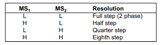
A3967B is a dedicated stepper motor driver chip for Bipolar motors. This chip uses microstepping method to drive the stepper motor with built in translator. The in built translator in this chip translate pulse signal in its “STEP” pin and drives the stepper motor by pre-determined resolution. The resolution of stepper motor is determined by logic input to MS1 and MS2. In the above circuit MS1 was set to logic 0 while MS2 was set to logic 1. This commands the chip to drive motor by quarter steps which gives 22.5 degree per step. Check out the datasheet of A3967 for better understanding.
You can change the logic input to MS1 and MS2 pins in order to change the resolution of your motor. This IC can deliver a current of 750mA and operates at a maximum voltage of 30v. You may have to choose your stepper motor that matches with these specifications.
555 ASTABLE MULTIVIBRATOR:
Timer IC 555 is used as astable multivibrator to generate square wave pulse. Here the reset pin of 555 is connected to the switch S2. When the switch is not pressed resistor R4 will pull the reset pin which will pull the reset pin to low state. This results low or logic 0 output from astable multivibrator as well. This will result in logic “0” input to stepper motor driver A3967SLB. Therefore the motor will not rotate. When switch S2 closes it will pull the reset pin of 555 IC high. This will activate multivibrator and it will generate square wave pulse signal. This pulse input goes to “Step” input and drive the stepper motor continuously in the assigned direction. With each incoming pulse to “STEP” input pin from multivibrator motor will move one step per pulse. If switch S2 is being in pressed state motor will rotate continuously.
The frequency of output pulse is around 7khz. The resistor R1, R2 and C1 decides this frequency. This will give a logic “1” time period of 100us. According to A3697 datasheet input pulse to step input should have high signal time of about 1us and we have set our pulse to be 100us which is well over the required pulse time. Hence the step signal will drive the motor without any trouble. Do take this into consideration if you try to modify this above circuit.
NOTE:
You can only use Bipolar motors with this circuit
Make sure your motor is well within the driving capability of driver IC
You can also use toggle switch and pull down resistor set up with MS1 and MS2 pins for changing the motor resolution easily.
Hope this circuit was useful to you. Check out other Controller circuits in our website. If you have any queries / feedback do leave them in the comment box below.Follow our website through Social media, we publish circuits every Wednesday.

 This driver circuit is intended to control bipolar stepper motor using microstepping method. This is where step current is applied in the form of sinusoidal waveform. As a result this increases the accuracy of steps and reduces noise of stepper motor. In this circuit two switches can be used to control the direction and motion of stepper motor. Switch S1 is a toggle switch where toggling switch position will switch the direction of rotation of the stepper motor. Switch S2 is a push button to turn the motor ON and OFF. A pulse signal is necessary for the driver to make motor take progressing steps. To do that switch S2 is used with 555 multivibrator to enable pulse generation.
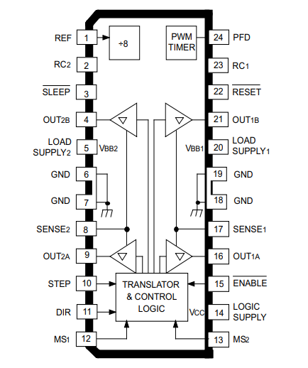
 You can change the logic input to MS1 and MS2 pins in order to change the resolution of your motor. This IC can deliver a current of 750mA and operates at a maximum voltage of 30v. You may have to choose your stepper motor that matches with these specifications.


Most Helpful and important information.
Thank you so much