 |
| PWM LED light dimmer circuit |
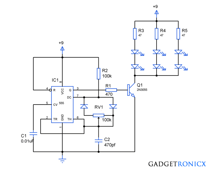
PWM ( Pulse Width Modulation) is a modulation technique in which the width of the pulse is varied based on the modulating signal. This possess wide variety of applications including motor speed control which is the most famous application of the PWM. This PWM led dimmer circuit uses IC 555 to generate PWM which is employed to dim the LED’s connected to the IC.
WORKING OF PWM LED DIMMER CIRCUIT:
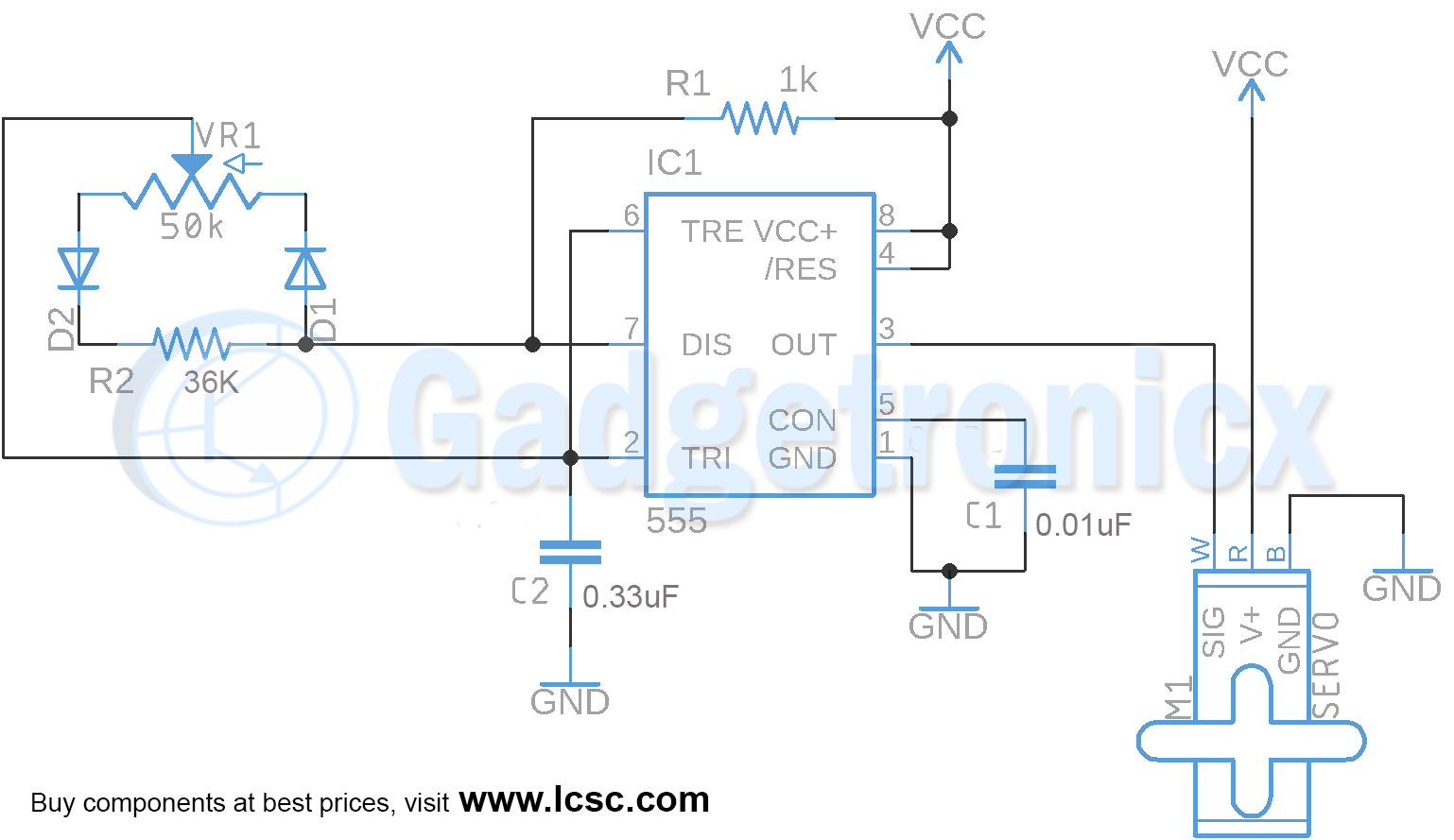
555 timer IC a widely used one was used to generate the PWM signal here. Here the IC was wired as an Astable Multivibrator which gives square wave pulses as output in pin 3. The output frequency of the the Multivibrator was governed by the values R2, RV1 and C2. Here change in resistance value of the RV1 alters the width of the output pulse thereby generating a PWM signal in the pin 3.
The generated PWM signal is fed into the base of the transistor since the 555 cannot source sufficient current for the working of LED’s. In the above circuit we have used white LED’s which consume 30mA and forward voltage of 3.5v. The above dimmer circuit can be used for two purposes here one is to produce dimming effect in the LED’s whereas another one is to save power consumed by the LED’s.
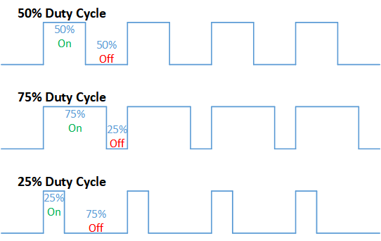
Using PWM signal we can reduce the on time of the LED in the above circuit which makes the circuit to consume less power. Around 70% – 80% PWM duty cycle it will switch as fast so that the human eye cannot see the flickering in the LED’s. The duty cycle of the PWM signal can be adjusted by varying resistance in RV1 and should be altered till no flickering is observed through our eyes. So through this way we can obtain desired luminescence with less power consumption.
Dimming of LED’s works the same way as above and should be done manually. You should vary the Resistance through the RV1 and this create an interesting dimming effect in the LED’s because of the varied on and off time of the PWM signal.



If electrical engineers wrote computer code examples….
a simple program:
for(x=0;x<12;x++) {
print "Hello ";
}
print "World\n";
//which outputs:
"Hello Hello Hello Hello Hello Hello Hello Hello Hello Hello Hello Hello World"
But then representing that program on my website like:
"Hello" "Hello"
"Hello"
print "World"
"Hello" "Hello"
for "Hello"
x++
"Hello"
print
"Hello"
x<12
"Hello" "Hello" "Hello" "Hello"
;;;;; :outputs which
"Hello"
Why in the hell can't you guys draw a circuit with the pins in the ACTUAL LOCATIONS AS THEY ARE ON THE CHIP?!?!
I understand your frustration, Scott. The reason why the pins on IC schematic symbols do not correspond to the physical pin layout is, in short – they don’t need to. By convention and common practice, pins are located on the schematic symbol according to function. Power pins are usually on the top of the symbol, ground on the bottom, inputs on the left, and outputs on the right. This improves the legibility and flow of the schematic. If you have ever seen a schematic of any complexity that doesn’t follow this convention, you will know how hard it is to interpret.
This convention goes back a good hundred years, to tube (valve) equipment designs. Engineers, PCB designers, and test technicians all understand this convention, and it hasn’t been replaced in more than a century. It’s now an industry standard (ISO 01.100.25), for the reasons mentioned above.
Will this circuit work with 4 different color leds? And with a supply voltage of +5V?
Erick,
5mm LEDs should work. But it’s better to check the forward voltage of the LED you want to use. Anything from 2 to 2.2v should work fine when Vcc is +5V
One question, the led supply voltage could be 60V Maintaining the supply of 9 of the 555. It is to control a fluorescent type led strip. thanks.
What is diode number???
1N4001
can any one share this ckt layout for pcb…?
Amman,
Will add in the article soon.
how do i know that duty cycle of output pulse is 70-80%
Adjust the pot until until there is no flicker in the LED’s or you can also determine the duty cycle using the below formula
Duty Cycle = (R2+RV1)/(R2+2RV1)
can i use this circuit used for any pwm application?
Of course you can PWM has tons of applications.