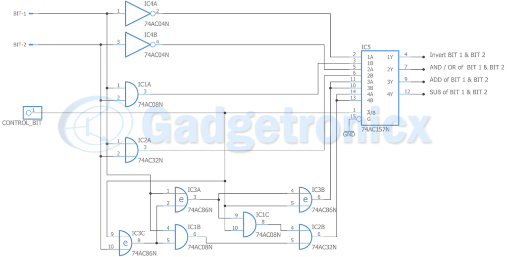
Arithmetic and Logic unit popularly known as ALU’s are essential part of digital systems and devices. Since it is a basic building block for digital systems we all must have built one in our engineering or high school. Apart from strengthening our understanding with digital circuits, its fun to build these kind of logic circuits. In this article you will see a simple 2 bit ALU circuit that uses inverters, AND, OR gate, Ex-or gate and a multiplexer. It takes two input bits.
Outputs:
Inversion of Bit 1 and Bit 2
AND of Bit 1 and Bit 2
OR of Bit 1 and Bit 2
Add of Bit 1 and Bit 2
Sub of Bit 1 and Bit 2
WORKING OF 2-bit ALU circuit:
For this circuit we have three input bits. Two input bits and a control bit. Control bit feeds to multiplexer chip and allows user to switch between outputs as mentioned in the above circuit.
To perform the AND operation we simply use an AND chip 7408 and OR operation using 7432 chip. Two Inverter chips 7404 for invert operation of Bit 1 and 2. A half adder and subtractor is built using 7486, 7408, 7432 chip to perform addition and subtraction operation for Bit 1 and Bit 2.
The output from these inverters, Adders, Subtractors, Add and OR operation goes to multiplexer. The control bit will select the output in pins 4, 7, 9, 12. Let’s take pin 4 and 7 first , if control signal is 0 these 4th pin of multiplexer shows invert output of Bit 1 and control signal 1 exhibits invert output output of Bit 2.
For pin 7 of multiplexer if control signal is 0 / 1 output at pin 7 will be AND or OR operation of Bit 1 and Bit 2. The output pins 9 and 12 will correspondingly show ADD and Subtract output of Bit 1 and Bit 2 despite the state of control bit.


 RF Remote control circuit")


 using LED's")