
Cooking can be grueling experience if kitchen is not ventilated properly. Despite good ventilation sometimes we need an exhaust fan to moderate the temperature in kitchen while cooking. But when we are so busy cooking, we often forget the fan and end up cooking without it. A simple solution to this problem is to use a circuit to automate the exhaust fan in your kitchen to turn on when you start cooking and off when you are done. This Automatic exhaust fan circuit uses a temperature sensor to monitor the atmospheric temperature and turns the fan ON or OFF based on the temperature. Check out a similar exhaust fan circuit for your bathroom which turns the fan ON when someone uses the commode.
Working of Automatic exhaust fan circuit :
LM50 temperature sensor:
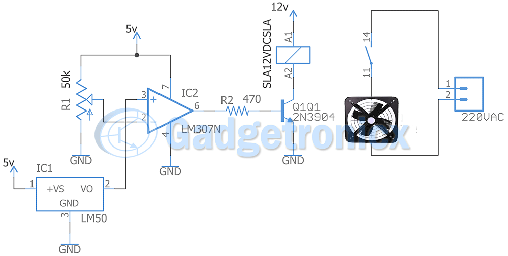
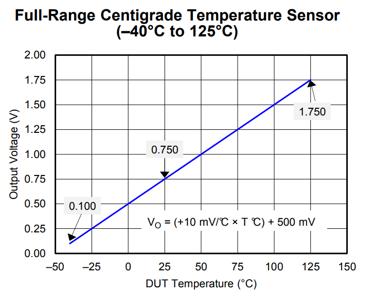
The working of this circuit starts with LM50. This is a temperature sensor which can measure temperature from -40 to 125 degrees. Our point of interest is 35 to 40 degree depends on the place you live. This will be the approximate temperature range in a kitchen when we start cooking. This temperature range falls well within the capability of sensor. This output of this sensor varies with 10mV with change in 1 degree of temperature. If we work within 35 to 40 degree temperature, the output of this sensor will fall within 0.75 to 1v. You can observe this in the below graph.
The output from this sensor is fed into non inverting terminal of an opamp which is wired as comparator in this circuit.
Comparator:
A 50k pot is connected to inverting terminal of LM307 to give the reference voltage. Modifying this pot will modify the input voltage fed to inverting terminal of LM307. Remember you must alter this pot’s resistance so that the input voltage will range from 0.75v to 1v. You can substitute 50k resistor with 100k resistor for more precision. Upon comparing the pot’s input voltage with LM50 output voltage comparator acts accordingly.
Set the pot’s input voltage to desired level. Remember this should be slightly less than LM50 output voltage at normal room temperature when you are not cooking. You may want to measure LM50 voltage at normal temperature and set the pot resistance accordingly to get the desired voltage. When you begin cooking, temperature increases. This will result in increase of LM50 output voltage. When this voltage exceeds input voltage from pot, output of LM307 goes high and activates the transistor.
Transistor and Relay:
The output of LM307 activates the transistor. This allows the current flow through the collector and in turn the Relay turns ON. This relay closes the circuit and turns the fan ON. The given Relay SL12VDCSLA operates at 12v and capable of handling load of 20A. Most of the exhaust fan consumes less than 2A so this relay is a viable choice. If in doubt check out your exhaust fan maximum ratings and choose your relay accordingly. Also remember if you are choosing a different relay ensure the coil current does not exceed collector current of the transistor you use.
By this way the Fan will automatically turn ON when you start cooking or when there is a temperature rise. It continues to stay ON until the temperature drops.
Note:
- Calibration is quite important to this circuit. Measure the LM50 output voltage before and during cooking to obtain the preset voltage you need to set using pot resistor.
- Pay attention to Exhaust fan current to choose right relay, likewise choose the right transistor to activate the relay.
I believe this circuit was useful to you, try out this hack in your kitchen. Check out our circuits library for more circuits each categorized for easier browsing. Please leave your comments/ feedback in the below comments section.


