We are turning everything around us smart with the help of technology, why leave your exhaust fan out of this smart circle? Here is a very simple circuit that can make your exhaust fan smart which in turn saves power consumed in your home. You can adapt this circuit for other utilities in your home like cupboard lighting, Room lighting and so.
HOW IT WORKS:
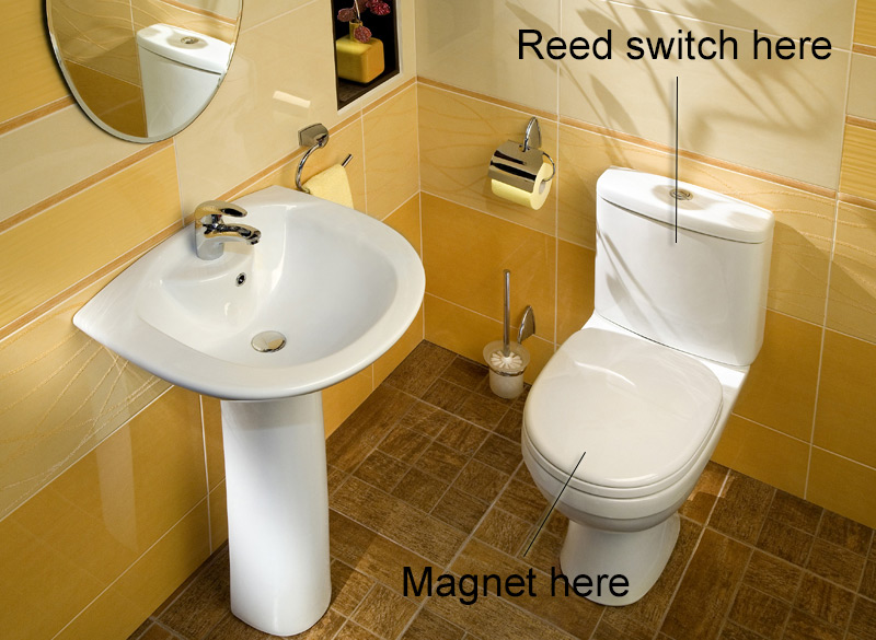
This circuit is designed to automate the turning ON and OFF of exhaust fans in your bathroom. Almost every houses have exhaust fans set up in their bathroom in a way when the lights are turned ON exhaust fans are turned ON as well. That’s just waste of power when we really don’t use the toilet commode. In this circuit we are going to set up a simple magnet and reed switch like shown above. Doing this whenever the lid of commode is opened, it will activate the exhaust fan. This way you will be able use exhaust fan when appropriate and stop wastage of power.
WORKING OF SMART EXHAUST FAN CIRCUIT:
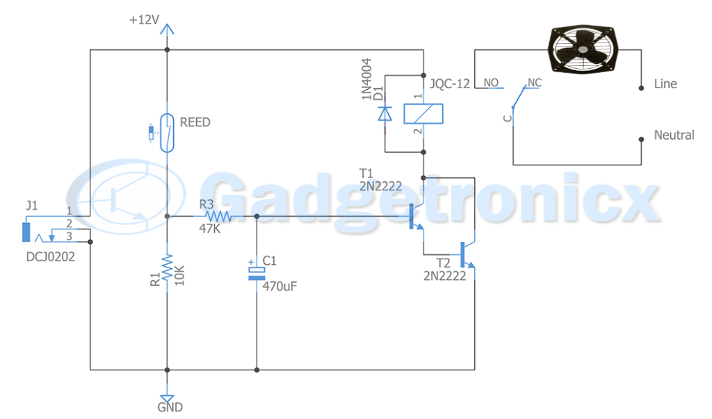
Reed switch acts as key element in this circuit. Whenever a magnet comes in contact with reed switch, it closes the electrical contact thereby allowing current to flow through it from +12v supply. This then goes to a RC timing element formed using R3C1. The main purpose of this timing element is to delay turning ON of fan in order to avoid accidental activation. The delay generated by the R3C1 pair is about 2.29 secs which is a fair time delay in order to detect the correct activation of reed switch. The delay is governed by the given formula
t = R3C1 ln ( Vcc / Vcc – Vc ), here Vc is the capacitor voltage which is equal to 1.2v ( VBE ) of darlington transistor pair Q1 & Q2
Substituting the values in the above formula will give
Once the delay of 2.29 secs is over the darlington transistor pair made out of Q1 and Q2 gets turned ON.
BASE CURRENT:
Let’s calculate the base current to this darlington pair
Ib = 12V / 47k = 255uA
This current is too low for a single transistor to activate a relay. Hence we have used a darlington transistor pair as switch here, which provides better sensitivity to base current and can handle large collector or relay current in this instant. According to datasheet of 2N2222 transistor it’s individual minimum gain is 35 whereas when putting it together as a darlington pair we could get a gain of about 1225. This will enable us to provide a minimum collector current of about 300mA to the relays. In our case this is sufficient to activate the relay and in turn activate the exhaust fan. Once the exhaust fan gets turned ON, it will continue to be in that state until commode is closed with its lid.
NOTE:
Before implementing this circuit there are two design considerations
Check your relay current and make sure your darlington pair can handle it.
Check the current rating of your exhaust fan and choose the relay is capable of turning it ON.