Pulse width modulation aka PWM is a popular digital modulation mostly used in controlling motors, lights, power supplies, heating devices etc. ATtiny85 has in built feature to generate PWM signal of variable frequency and duty cycle. This PWM generation by ATtiny85 is possible using timer (tutorial here ) and compare match module (tutorial here).
ATtiny85 can generate two types of PWM signals : Fast PWM and Phase correct PWM each has varied characteristics. This tutorial will cover configuration of ATtiny85 microcontroller to generate PWM signal with desired frequency and duty cycle. In Attiny85 there are two timers which we can use to obtain PWM signals from these 4 pins PB0, PB1, PB3, PB4.
How PWM signal is generated:
PWM in ATtiny85 is generated by the combined action of timer and compare match. When timer is configured and starts running the timer value increments in TCNT0 register. The incremental timer value will be compared against the value stored in compare match registers OCR0A and OCR0B. When value in the TCNT0 matches with either OCR0A or OCR0B register the pulse output from PWM pins PB0, PB1, PB3 or PB4 switches based on the configuration. This results in generation of variable width pulse in the output ( will see about this in detail below ).
Fast PWM mode:
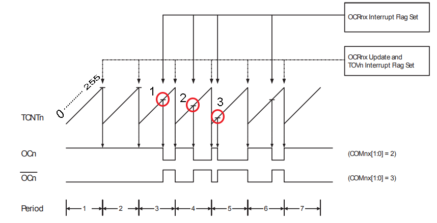
Fast PWM mode provides a way to generate high frequency PWM waveform. It operates based on a single slope operation as you can observe in the above diagram. In this mode the timer value in TCNT0 starts from BOTTOM that is 0 and counts up to TOP that is 255. Upon reaching maximum value of 255, it restarts its count from BOTTOM ( single slope operation ).
The value in TCNT0 will be compared against OCR0A and OCR0B register. Whenever a match occurs the output waveform switches its current state. These spots are marked as 1, 2 and 3 in the above diagram. These compare matches result in the pulse waveforms that has varied width ( OCn and OCn’ ) as shown in the diagram. The compare match with OCR0A will be exhibited in OC0A (PB0) pin and OCR0B will be exhibited in OC0B (PB1) pin. By changing the values in OCR0A and OCR0B register the width of the pulse can be changed.
Let’s say the value in OCR0A is 200. The timer starts counting from zero. When the non-inverting mode is selected, OC0A will be high from 0 – 199. Upon compare match on 200 the output will be cleared to low. OC0A will remain in low state from count 200 – 255. The OC0A will set back to high when TCNT0 goes zero. This will give a PWM signal of duty cycle
0 to199 – High pulse, 200 to 255 – Low pulse
Duty cycle = ( 200 / 255 ) x 100 = 78.41%
The frequency of the waveform when using Fast PWM mode is given by the formula
fPWM = fclk_I/O / N. 256
where N above represents prescale factor ( 1, 8, 64, 256 or 1024 )
Phase Correct PWM
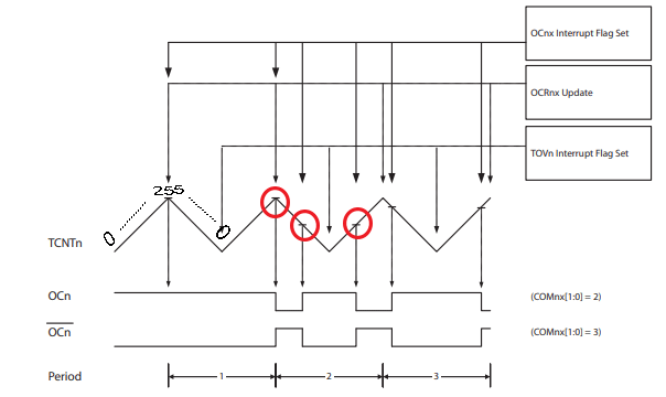
Phase correct PWM uses dual-slope operation opposes to Fast PWM. This means timer value at TCNT0 starts at the BOTTOM ( zero ) and counts to TOP ( 0xFF ). On reaching top it starts decrementing from 255 and then count to BOTTOM ( zero ). Due to this the maximum frequency of signal in Phase correct PWM mode will be half the maximum frequency in Fast PWM mode.
The PWM operation is pretty similar to Fast PWM. Timer value increments in TCNT0 register and will be compared against OCR0A and OCR0B registers. When a match occurs between TCNT0 and OCR0A/ OCR0B register output signal at OC0A and OC0B pin switches as shown in the above diagram. Altering the values in OCR0A and OCR0B register will alter the duty cycle of generated PWM signal. The set / clear ( switching ) of OC0A / OC0B pins upon compare match can be configured. Therefore both inverting and non inverting PWM signal from ATtiny85 is possible.
Duty cycle for Phase correct PWM:
Let’s say the value in OCR0A is 150. The timer starts counting from zero. When COM0A1 and COM0A1 bits are configured as 1, OC0A will be high from 0 to 149. Upon compare match on 150 the OCR0A will be cleared to low. After counting up to 255, TCNT0 decrements and upon reaching 150 during down counting OCR0A will be again set to high. OC0A will remain in low state from count 200 – 255. The cycle repeats thus generating a PWM signal.
0 to 149 – HIGH pulse & 150 to 255 – Low pulse ( Upcounting )
255 to 150 – Low pulse & 149 to 0 – High pulse ( Downcounting )
OC0A will be high for – 150 + 150 ( TCNT0 counts )
Duty cycle = ( 300 / 512 ) x 100
= 58.59%
The frequency of Phase correct waveform can be given by
fPWM = fclk_I/O / N. 510
where N above represents prescale factor ( 1, 8, 64, 256 or 1024 )
Configuring ATtiny85 for PWM generation:
We will now look into how to configure ATtiny85 to generate Phase correct PWM signal.
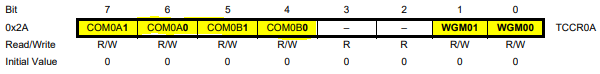
TCCR0A – Timer/Counter Control Register A
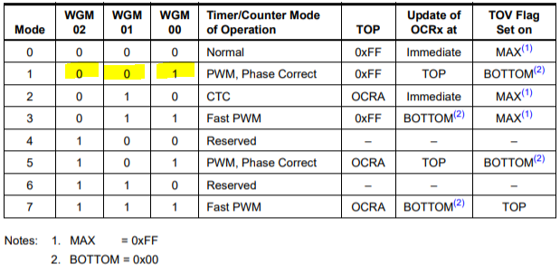
Using the TCCR0A register we have to choose the Phase correct PWM mode. This mode of operation will set the timer to be start from zero and reach the maximum value of 255 with an upside increment in counting and again starts down-counting and reaches to zero. The bits WGMO2, WGM01 has to be set to zero and WGM00 has to be set as one. Note : WGM02 bit will be in TCCR0B register.
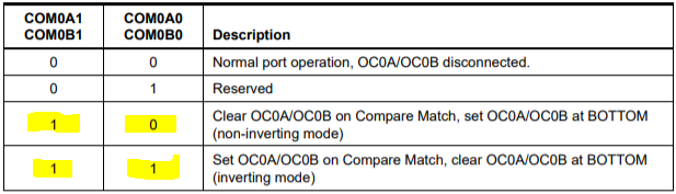
Bits COM0A1, COM0B1, COM0A0, COM0B0 are used to set when clear, set will occur.
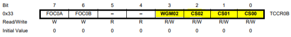
TCCR0B – Timer/Counter Control Register B
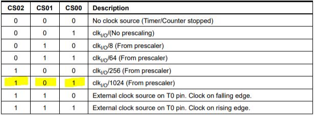
Bits CS02, CS01 and CS00 are used to set the clock frequency speed at which the timer operates. This will affect the frequency of generated PWM signal. In this tutorial am looking to control the speed of motor using generated PWM. For this reason we will choose the lowest speed and therefore prescale the timer clock by a factor of 1024. To do that we have to write 101 to bits CS02,CS01,CS00 as shown in the below table.
This will set the frequency of PWM signal to 31.59Hz. This is based on the formula you have seen earlier in Duty cycle for Phase correct PWM section.
fpwm = fclk /(N x 510)
= 16.5MHz/(N x 510)
= 31.59Hz (if N=1024)
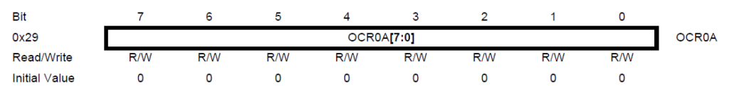
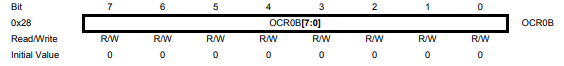
Output Compare Register OCR0A and OCR0B:
The output compare registers OCR0A and OCR0B which should be used to store values to compare against TCNT0 register. These are 8-bit registers so user can use any value ranging from 0 to 255.
Steps to configure Phase-correct PWM:
Configure the PWM pins PB1 and PB0 as output using DDR register.
Select the Phase correct PWM mode and clear, set instances in TCCR0A register.
Prescale the timer clock if necessary
Based on duty cycle calculation store the required value in OCR0A and OCR0B registers.
You will obtain corresponding PWM signal to these matches in OC0A and OC0B pins.
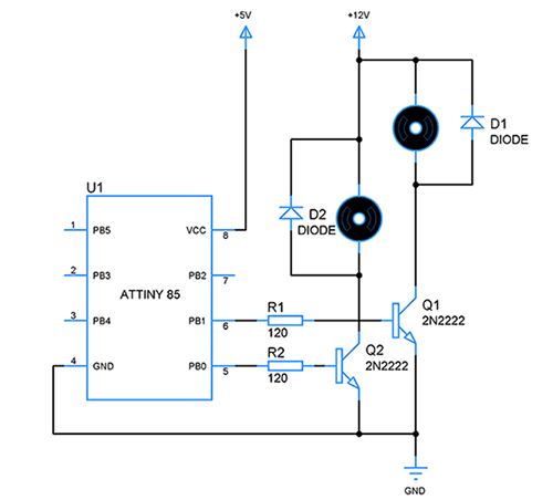
Circuit diagram:
For the purpose of this tutorial we have used two 12V motors and control its speed using PWM signal generated by ATtiny85. ATtiny85 cannot drive these motors directly so a transistor is necessary to switch the motors safely. PB0 is OC0A and PB1 is OC0B.
Code for Phase correct PWM:
#include<avr/io.h>
#define F_CPU 16500000UL

void PWM_config()
{
DDRB =(1<<PB1)|(1<<PB0); // set PB1 and PB0 as output to enable PWM generation
TCCR0A=0x00;             //Normal mode
TCCR0A|=(1<<WGM00)|(1<<COM0A1)|(1<<COM0B1)|(1<<COM0A0)|(1<<COM0B0);
TCCR0B=0x00;
TCCR0B |= (1<<CS00)|(1<<CS02);   //prescaling with 1024
TCNT0=0;
OCR0A=150;            //Generating PWM of 58.9% duty cycle from OC0A
OCR0B=250;           //Generating PWM of 98% duty cycle from OC0B
}

int main()
{
  PWM_config();
  while(1)
  {

  }
}
Hope this tutorial was useful to you. You can find more ATtiny85 tutorials here. Post your queries and feedback in the comments section below.
Need to use external clock for frequencies outside of the five pre-programmed 3bit settings for timer. An adjsutable timer cky using 555 as example.
As for PWM %, OCR0A number is a high period as the timer counts up to 255 and back down to 0 (512 steps),
so %PWM = ((OCR0A * 2) / 512) * 100
0CR0A = DutyCycle * (512/200)
0CR0A = 26 * (512/200) = 66.56
What do I need to replace in phase correct codes to produce up to 4 pulses?. My instructor gave me a code for a single pulse and ask I should add more codes to generate more pulses. I had copied and paste his code but do not know what to replace to general more pulses in phase correct.

 For the purpose of this tutorial we have used two 12V motors and control its speed using PWM signal generated by ATtiny85. ATtiny85 cannot drive these motors directly so a transistor is necessary to switch the motors safely. PB0 is OC0A and PB1 is OC0B.


Hello,
how do i get a frequency of 1KHZ
and a duty cycle of 26%
Need to use external clock for frequencies outside of the five pre-programmed 3bit settings for timer. An adjsutable timer cky using 555 as example.
As for PWM %, OCR0A number is a high period as the timer counts up to 255 and back down to 0 (512 steps),
so %PWM = ((OCR0A * 2) / 512) * 100
0CR0A = DutyCycle * (512/200)
0CR0A = 26 * (512/200) = 66.56
%PWM = ((66.56 * 2) / 512) * 100 = 26
What do I need to replace in phase correct codes to produce up to 4 pulses?. My instructor gave me a code for a single pulse and ask I should add more codes to generate more pulses. I had copied and paste his code but do not know what to replace to general more pulses in phase correct.
4 pulses of PWM signal?
Just set your PWM and frequency, then loop it just 4 times.
Inside the chip, the counter needs to count 0-255 and then 255-0 four times to get 4 pulses.
Utility/delay.h – never used
Interrupts – not activated
??