LED based music spectrum is quite famous and almost everyone would have used music systems which has one of these. With some components, LEDs and some wires we can make this type of music spectrum. But here in this circuit instead of making the LEDs react to music it reacts to ambient sound or noise level. It uses microphone to monitor the sound in environment and based on the intensity of ambient sound LED will light up. Higher the intensity of sound more LEDs will light up making it a sound level meter to use in places such as libraries, classrooms etc.
Working of Sound level meter:
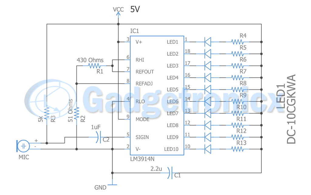
This circuit uses a electret microphone which is powered using a pull up resistor R3 . When there is a sound in the environment Electret microphone picks it up and this signal will go to pin SIG IN pin through Capacitor C2. This Capacitor C2 removes DC components in the signal. Now the IC LM3914 takes over. Looking at the datasheet of LM3914 , it takes analog signal input and compares with internally set voltage reference, then drives 10 outputs based on it. It is widely used to drive LED’s and LCDs.
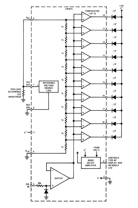
Let’s take a look at it’s internal diagram to understand this better. Ref out pin of this chip delivers a fixed 1.25v. This 1.25v determines the change in input voltage given to SIGN IN pin at which output advances from pin 1 to pin 10 lighting up the LED’s in sequence. This voltage input from SIG IN pin will be compared with series of comparators inside this chip and each comparator pulls its output to low when voltage at SIGN IN exceeds comparators reference voltage. This implies if you gradually increase voltage input to SIG IN pin above 1.25v, LED 1 connected to pin 1 will light up first. When voltage input reaches 2.5v LED 2 in pin 18 lights up. Therefore increment in 1.25v at SIG IN pin LED advances the output by one step.
Modifying the reference voltage:
1.25v reference voltage per step is quite too much for our sound level meter. So we set up a simple voltage divider to drive REF ADJ pin which is responsible for changing the above reference voltage. We have setup a voltage divider of using R1 ( 430 ohms ) and R2 ( 51 Ohms ).
The output voltage of this voltage divider setup is 0.13v. This means the output LED lighting sequence increments when there is a 0.13v increment in input signal from electret microphone.
We choose 0.13v reference voltage which is quite low since we need our circuit to be extremely sensitive to ambient noise. Alternatively you can substitute the values of R1 and R2 to suit your need.
As per the datasheet, the current drive of output pins can also be modified. It will be ten times of the current draw from REF OUT pin. Typically to use this IC we should use a load resistor to draw current from this pin even if you want to stick with internally referenced voltage of 1.25v. Here we have set up a voltage divider to this pin. The current draw by this voltage divider from REF OUT pin will be
I = 1.25 / ( R1 + R2 )
= 1.25 / ( 430 + 51 )
= 2.5mA
Using this we have set the maximum current flow into the output pin as 25mA. This is sufficient to drive LED’s which typically takes maximum of 30mA. The value of resistor R4, R5, R6, to R13 is 100 ohms, which drops the voltage from 5v to forward voltage of LED ( 2.2v). Usage of 2.2uF, a bypass capacitor is used from LED’s to ground terminal to prevent oscillations.
Partlist:
Power supply – 5v
C1 – 2.2uF
IC1 – LM3914
Bar graph LED
R1, – 430 ohms
R2 – 51 ohms
R3 – 5k
R4, R5, R6, ……..R13 – 100 ohms
Note:
Use only a load resistor with REF OUT pin to fix only the current draw for LED’s which is ten times the current draw from REF OUT pin.
Use a voltage divider network with REF OUT pin if you intend to reduce the reference step voltage from 1.25 but also consider the current draw by your voltage divider will fix the current draw by LED’s in output.
Hope this Circuit is useful to you. If you have any queries or suggestion about this circuit. Do post them in the comments section below. Also check out our Electronics circuits library for more circuits categorized for easier browsing.


Hi,
Where do I get a 5K resistor?
It’s not a standard value.
Usualy is 5.1K or 5.6K