Comparators in electronics are used to compare two input analog signals and output a digital output based on it. Popularly we use dedicated comparator chips for this purpose, however with ATtiny85 we have in built analog comparator which can perform this comparison. This peripheral works closely with Analog to digital converter of ATtiny85. This tutorial explains how to configure ATtiny85 to use as comparator and pins to use with it.
In ATtiny85 the analog comparator peripheral uses AIN0 ( PB0 ) pin as positive input and negative input can be chosen from any one of following pins : AIN1 ( PB1) and ADC input channels – ADC0, ADC1, ADC2, ADC3.
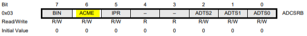
ADCSRB – ADC Control and Status Register B
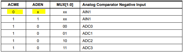
ADCSRB register is also used primarily for configuring ADC in ATtiny85. However for Analog comparator we use this bit ACME ( Analog comparator Multiplexer enable bit ) to select the negative input to comparator. When this bit is zero, multiplexer will be off and AIN1 will be the negative input to comparator. When it is set as 1 and ADC is disabled by writing ADEN as zero ADC input channels – ADC0, ADC1, ADC2, ADC3 can be used as negative input ( explained further below ).
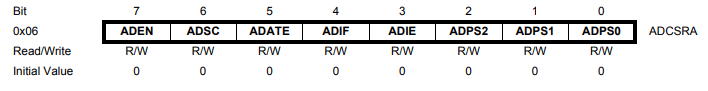
ADCSRA – ADC control and status register A
ADEN bit enables or disables usage of ADC. Disabling the ADC by writing ADEN as zero will allow user to use ADC channels – ADC0, ADC1, ADC2, ADC3 as negative input to comparator.
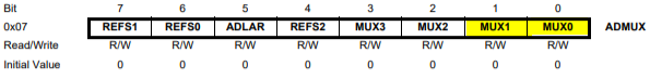
ADMUX– ADC Multiplexer Selection Register
Upon disabling ADEN in ADCSRA register and enabling ACME in ADCSRB register we can select any one of the ADC channel to use as negative input to comparator using Multiplexer bits MUX1 and MUX0. The below table shows the bit selection of these bits and their corresponding channel selection.
By making ACME clear we can use AIN1 as negative input to the comparator.
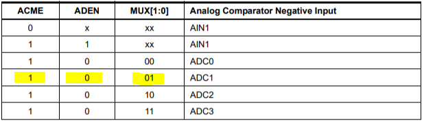
Using ADC1 as negative input:
By setting ACME as 1 and using the corresponding mux inputs we can select any one of the ADC channel. Here we are using ADC1 channel so we need to give 01 input to the MUX1, MUX0 bits.
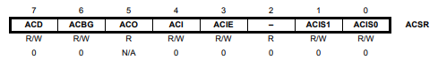
ACSR – Analog Comparator Control and Status Register
The bit 7 of the Analog comparator control register is used to turn on/off the comparator. If it is set then the power to the analog comparator will be switched off.
The bit 6 ACBG Analog comparator bandgap select serves to select bandgap reference voltage as positive input to comparator. This is typically 1.1v for ATtiny85 microcontroller. This bit will is not necessary for a typical comparator operation.
Bit 5 ACO is the output bit that gives the digital output of the comparator. This bit has to be read manually by the programmer to know the status of comparison. The output typically takes 1 to 2 clock cycles to sync with the input change.
ACI bit is the flag register that will be set when the comparator output meets the criteria set by ACIS1 and ACIS0 bits.
ACIE bit is the interrupt enable bit that enables interrupt to be triggered when ACI flag set by comparator.
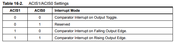
The below table shows the criteria that can be set using ACIS1 and ACIS0 bits to trigger interrupt events. This bit will not take effect if ACIE ( analog comparator interrupt ) is disabled.
Steps to configure Analog comparator using AIN0,AIN1 as inputs
Write ACME as zero to disable ADC multiplexer.
Read the ACO analog comparator output bit in ACSR register.
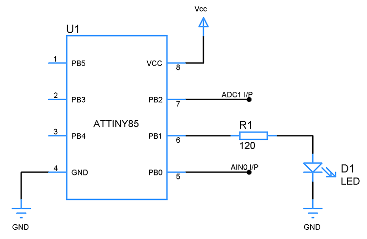
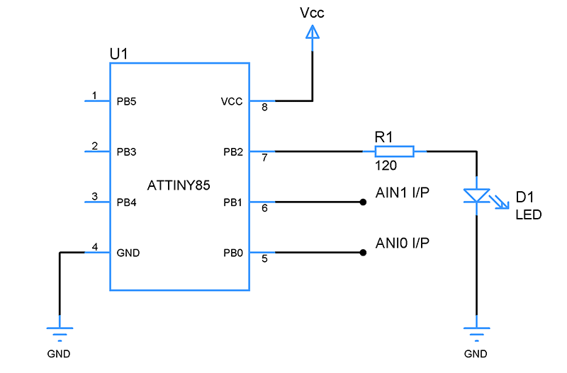
Circuit diagram for using AIN0 and AIN1 as inputs:
The above circuit uses PB1 and PB0 as negative and positive inputs to comparator. A LED to PB2 will act as an indicator to indicate the status of comparator output.
Sample code AIN0 and AIN1 as inputs:
#include<avr/io.h>
#define F_CPU 16500000UL

void comp_setup()
{
  DDRB|=(1<<PB2);          //PB2 as ouput to drive LED
  ADCSRA=0x00;            //Using AIN0 and AIN1 as comparator inputs
  ADCSRB=0x00;
}

int main()
{
  comp_setup();
  while(1)
  {
    bool comp_out=(ACSR & (1 << ACO));       //Reading ACO comparator output bit
    if(comp_out==1)                          //Positive input higher than negative input
      PORTB|=(1<<PB2);                       //LED goes high

    else if(comp_out==0)                     //Negative input greater than positive
      PORTB&=~(1<<PB2);                      //LED off

  }
}
Steps to configure Analog comparator using AIN0,ADC1 as inputs
Select ADC1 as non-inverting input by writing 1 to ACME bit and writing 01 to MUX1, MUX0 bits in ADMUX register.
Disable the ADC by writing zero to ADEN bit in ADCSRA register
Read the Analog comparator output bit ACO to determine the comparator output.
Circuit diagram for using AIN0 and ADC1 as inputs:
Sample code AIN0 and ADC1 as inputs:
#include<avr/io.h>
#define F_CPU 16500000UL

void comp_setup()
{
  DDRB|=(1<<PB1);
  ADCSRA=0x00;
  ADCSRB|=(1<<ACME);      //Enabling ADC multiplexer
  ADMUX=0x01;            //Using ADC1 channel as inverting input for comparator
  ACSR=0x00;
}

int main()
{
  comp_setup();
  while(1)
  {
    bool comp_out=(ACSR & (1 << ACO));       //Reading ACO comparator output bit
    if(comp_out==1)                          //Positive input higher than negative input
      PORTB|=(1<<PB1);                       //Light up LED

    else if(comp_out==0)
      PORTB&=~(1<<PB1);                     //Turn off LED

  }
}

 Sample code AIN0 and ADC1 as inputs: