Laser security alarm is widely adopted industries and other commercials. The reason behind this is that Laser is less prone to be affected by environmental conditions making it reliable and trustworthy. So in this Arduino project I have used Laser as a means of detecting intrusion and raise an alarm when intrusion occurs.
MATERIALS REQUIRED:
Keyes Laser module
Arduino Uno
IC 556
Resistors
Capacitors
Keyes Relay module
Power supply
LASER AND LDR FOR DETECTING INTRUSION:
The working of this project starts with Keyes laser module. When powered ON this module emits Laser which follows a straight path. On its path LDR is at the other end. This Laser module and LDR together forms the monitoring section of this module. The Laser module and LDR should be in a place like door path, windows etc. And this is where when someone enters or intrude will interrupt the path of Laser and cut off the beam from falling over LDR.
LDR ( Light dependent Resistor ) is a component that reacts to light. The resistance of LDR will be very low when Laser beam falls on it whereas its resistance will be very high when Laser beam is cut off from it. The LDR is setup as a voltage divider where the change in resistance will alter the output voltage of this voltage divider. This voltage divider will give high voltage when Laser beam is incident on LDR. And when the beam is cut off by burglar or intruder the voltage out of divider will be very low.
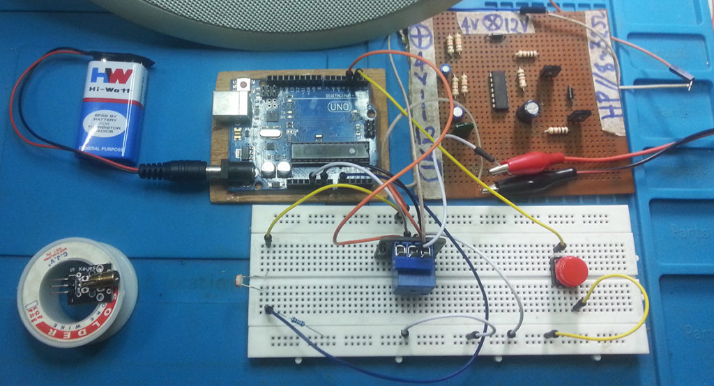
The above schematic diagram shows the connection for this entire project. The Keyes relay module is will emit laser beam over LDR. The voltage output from voltage divider setup up of LDR and resistor goes into the Analog input pin of A0 of Arduino. And the switch S1 is meant to turn off the alarm after it is triggered. The button S1 should be in the control of user and should not be accessible by the intruders.
The Arduino pin D3 controls the relay connected to it. Along with the relay an indicator LED is in circuit to indicate the alarm is ON. The relay activates the alarm circuit built around IC 556. I have used 8 ohm speaker for sounding purpose. The reason we use relay to activate the alarm is because Arduino cannot supply enough current to drive the entire alarm unit by itself.
/*
  Syldz@k
  Visit my blog, comment,share and...please make a donation !!!
  https://kazdlys.blogspot.com
*/
int ldr = A0, button = 2, relay = 3, threshold = 512;
void setup() {
  pinMode(ldr,INPUT);
  pinMode(button,INPUT_PULLUP);
  pinMode(relay,OUTPUT);
}

void loop() {
  int val = analogRead(ldr);
   while(val < threshold) {
    bool k = digitalRead(button);
    if(k != 0) {
      digitalWrite(relay, HIGH);
    }
    else {
      break;
    }
   }
  digitalWrite(relay, LOW);
  delay(1);
}
/*
  Syldz@k
  Visit my blog, comment,share and...please make a donation !!!
  https://kazdlys.blogspot.com
*/
NOTE:
The alignment of Laser module and LDR is very important so setup in the way it monitors your doorway and anyone comes through that intrudes the beam
You can replace the alarm section of the above project with your own alarm system but make sure that the relay used can handle the current requirement of your alarm.

 Laser security alarm is widely adopted industries and other commercials. The reason behind this is that Laser is less prone to be affected by environmental conditions making it reliable and trustworthy. So in this Arduino project I have used Laser as a means of detecting intrusion and raise an alarm when intrusion occurs.


")


