In the previous tutorial of ATtiny MCU series we have covered how to get started with this 8 bit MCU, Attiny85 and how to use its GPIO pin as an output. The second part of this series where we will explain how to configure its GPIO pins as input and how to read status of input pin. Here we will use a push button to feed signal to digital input pin and a LED as output. The LED state will be toggled based on the button input.
ATtiny85 GPIO input:
DDRB register:
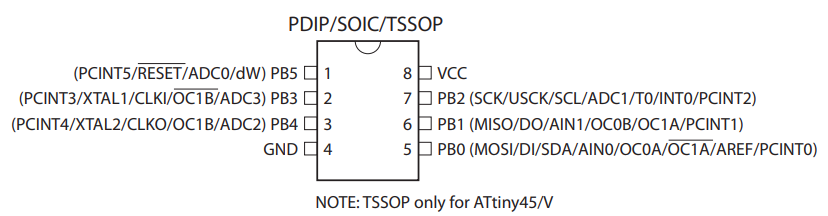
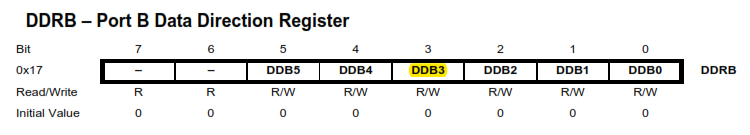
The configuration of ATtiny85 GPIO input pins starts with DDRB register, you can refer the datasheet here. We are looking to use pin 2 of attiny85 as Input. Now according to the datasheet the pin 2 is PB3 of PORTB. In order to make it as an Input we need to write the DDB3 register bit as logic ‘low’ or 0 in the code. The below piece of code will do that.
DDRB &= ~(1 << PB3);// Set the pin PB3 as input
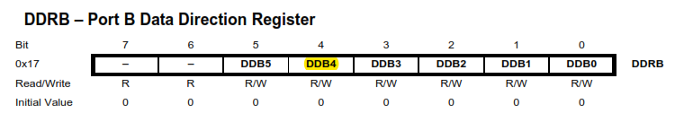
Similarly we need to define the pin 3 or PB4 as an output pin. Therefore the DDB4 register bit will be logic ‘high’ or 1.
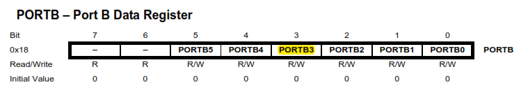
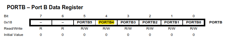
Now that we have configured the pins, we need to read the logic input from the input pin PB3. For that purpose we use PORTB register. PB3 is an Input pin, therefore we can not leave the pin floating when neither high nor low logic level are connected to it. So we need to activate the internal pull up resistor of this pin. To do that,
We need to set the PORTB3 register to 1. This register is generally used to set the output state of that pin high or low, but as we declare this pin as input, this will activate the internal pull up resistor.
PORTB |= (1 << PB3); //activate pull-up resistor for PB3
Alternatively you can use an external 10k resistor to pull-up or pull-down this pin.
PORTB register also enables to toggle the LED state high or low. Writing ‘1’ or ‘0’ to PORTB4 toggles the LED to ON state or OFF state.
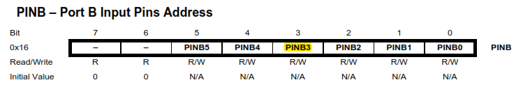
PINB register:
PINB register is where we can read the input of any pin that is configured as inpit. Here we will look for PINB3 bit value in this register without disturbing other bits.
We do that using the below line
buttonState = PINB & (1 << PB3);
Upon reading the input state we use this input to toggle LED ON and OFF. Like this,
if (buttonState) {
PORTB |= (1 << PB4); //write to PORTB register to set the LED state to HIGH
}
else {
PORTB &= ~(1 << PB4); //write to PORTB register to set the LED state to LOW
}
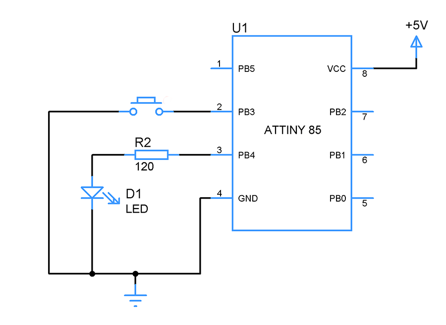
Circuit setup:
Sample code for ATtiny85 GPIO input :
Putting together the above pieces of code.
Edit: In IDEs like Atmel Studio 7 you need to include header file stdbool.h in order to use bool variables in the code.
#include <avr/io.h>

void setup() {

  DDRB &= ~(1 << DDRB3);  //set PB3 as input

  PORTB |= (1 << PB3);  //activate pull-up resistor for PB3

  DDRB |= (1 << DDRB4);   //set PB4 as output

}

void loop() {

  //read the button state

  bool buttonState = PINB & (1 << PB3);

  //if the button is HIGH, turn led on

  if (buttonState) {

   PORTB &= ~(1 << PB4); //write to PORTB register to set the LED state to LOW

  }

  //else, turn off

  else {

   PORTB |= (1 << PB4); //write to PORTB register to set the LED state to HIGH

  }

}
Try this out:
Configure PB0 and PB1 as input with internal pull up resistors enabled and button that connects to ground when pressed. Assign PB2 as output with LED connected to it. Write a code so that when button connected to PB0 is pressed LED in PB2 should turn ON and when button to PB1 is pressed LED should turn off.


You should probably mention that bool type variables are not normally usable, at least if using Atmel Studio 7, unless #include is included
stdbool dot h is library that is needed, this comment sections spam prevention probably cut away it as it could be interpreted as web addrwss
Thanks Ville for pointing this out. Updated the article with this information.