Compare match is a feature that is associated with timers and counters. This feature is available in most of the modern microcontrollers. It works by continuously comparing a particular value against the incrementing value in the actual timer register. When value stored in the register matches the value in timer register a match occurs. This feature will be extremely handy to generate accurate time delays compared to using stand alone timers and also to automatically check counter reaches against a threshold and to generate PWM.
In ATtiny85 two 8 bit compare match registers OCCR0A and OCCR0B can be used to compare against timer value register TCNT0. Also there are two pins OC0A (PB0) and OC0B (PB1) which can be toggled, set or cleared pins when compare match occurs. In this tutorial, we will use compare match feature to generate time delay of 1 sec by using both manual match flag manually and also using interrupt.
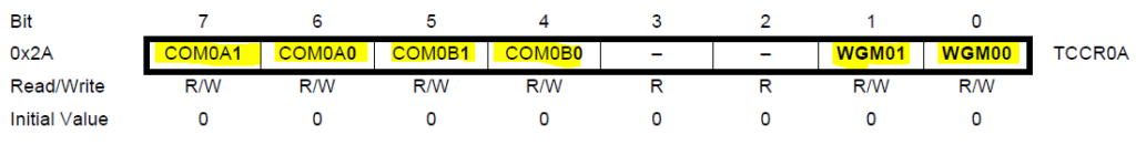
TCCR0A Register
In this register, the bits COM0A0, COM0A1, COM0B1 and COM0B2 need to be configured to use the compare match in the mode of operation we desire. The bits WGM01, WGM00 will be used to select clear timer on compare match ( discussed below ).
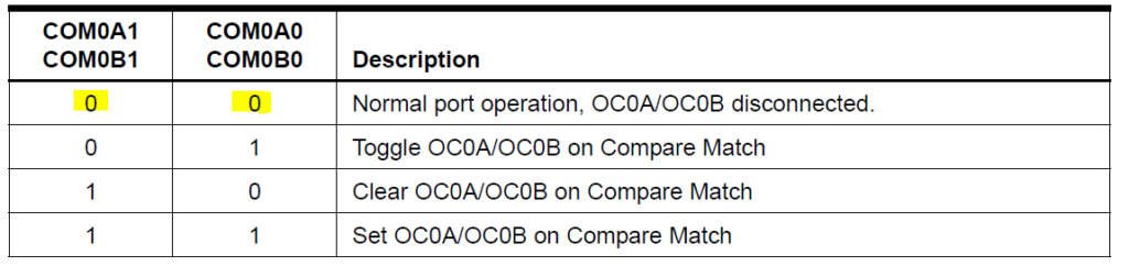
In this tutorial we set up the bits with 0 to run in the normal mode of operation without using OC0A (PB0) and OC0B (PB1) pins. If you intend to use these pins you can choose any of the following modes to take action such as Toggle, Clear and Set upon occurrence of compare match. beyond that.
The bits WGM0, WGM01 and WGM02 will be set to 010 to operate in the CTC mode. This means the timer value in TCNT0 register will count from 0 to the value in OCR0A register and once match occurs. The timer value will roll back to zero and continue counting towards OCR0A for next cycle. We chose this mode as this will enable us to generate precise fragments of time delay with each cycle.
Do note that when CTC mode is selected and if you need to use OCR0B as well. The value of OCR0B should be less than OCR0A since value in OCR0A defines the maximum value timer register TCNT0 can reach. Anything more than OCR0A in OCR0B result in non occurrence of compare match B at all. This doesn’t matter if you choose to operate timer in Normal mode.
TCCR0B Register
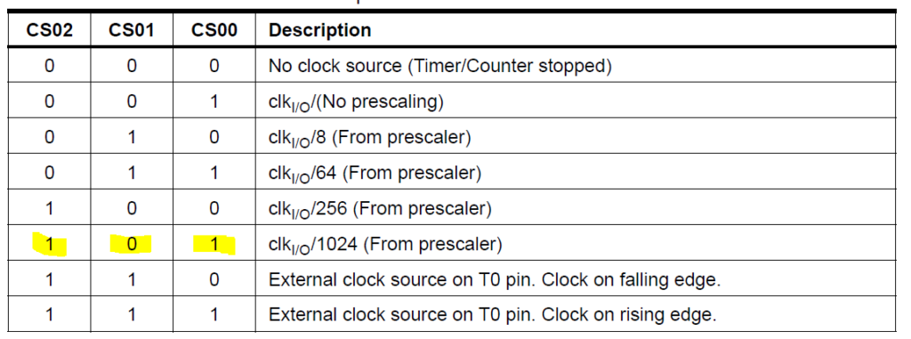
Do note that WGM02 bit is actually in TCCR0B register. CS02, CS01 and CS00 bits are used to select the prescaling factor for the incoming clock pulses.
Since in this tutorial we are looking to generate accurate time delay of 1 sec, we are prescaling by a factor of 1024 to slow down the rate of increment of values in TCNT0 register. If you are not familiar with the concepts of timer, check this ATtiny85 timer tutorial and come back here.
FOC0A and FOC0B bits are worth noting as writing 1 to these bits will force compare match and as a result the output pins OC0A and OC0B pins can be set, cleared or toggled on demand based on the desire of programmer.
Time Calculation
We need to generate a delay of 1 sec as accurate as possible. We are going to calculate the value of OCR0A that need to be compared with TCNT0 register to generate time delay of 1 sec. OCR0B is not necessary to do this so we are not going to use them.
The clock frequency of 16.5MHz is prescaled by 1024.
( 16.5 x 1000000 )/1024= 16113.28Hz
Time period = 1/16113.24Hz = 62.06us = 0.06206 ms
This is the time period that each count takes to increment in TCNT0 register. We are choosing to generate 10ms every cycle before timer rolls over to zero since 10ms will help us to generate 1000ms or 1 sec as accurate as possible.
Number of steps to reach 10ms = 10 / 0.06206
= 161.134
This is the number of steps that timer value in TCNT0 should increment to achieve close to 10ms time delay. Therefore this is the number that need to be stored in OCR0A to compare with TCNT0. But 161.134 is not a whole value and we can only store whole values in OCR0A. Therefore we choose the nearest value 161 to store in OCR0A.
161 steps will generate = 0.06206 x 161 = 9.991ms
This is close to 10ms. Now repeating this 100 times will get our time delay close to 1000ms
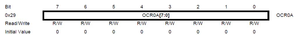
This register holds the value that need to be compared with TCNT0. In our case we will load 161 in OCR0A. This is a 8 bit register and capable of holding values up to 255.
OCR0B is very similar to OCR0A register.
Using manual monitoring of overflow flag
Now that we have seen what is Compare match and how it can be helpful. Let’s take a look at methods to use this feature. There are two ways you can use compare match.
Manual monitoring of compare match overflow flag
Using interrupts with compare match.
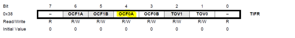
TIFR Register
TIFR is the flag register that holds the flag bits of timer overflow and compare match for Timer0 and Timer1 peripherals. After configuration of timer for compare match, when every time compare match occurs between OCR0A and TCNT0 occurs the flag bit OCF0A will be set to 1. Manually monitoring this flag will help you to identify when compare match occurs and act accordingly. This flag needs to be written 1 in order to clear it.
In our case this flag will be raised 161 times to achieve our 1 sec time delay. The flag bit OCF0B need to be read in case if you are using OCF0B register to compare with TCNT0.
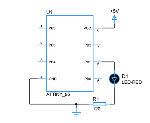
Circuit diagram:
Steps to configure compare match and manually reading overflow flag
The below steps were written in the context to generate 1 sec time delay and toggle LED connected to PB1 using compare match with OCR0A register
Select the normal operation and CTC mode for timer0
Pre-scale the internal clock by a factor of 1024
Store the desired value (161) in OCR0A
Timer0 operates and increments values in TCNT0 register
Monitor the OCF0A flag to see if match occurs between TCNT0 and OCR0A.
Clear the OCF0A flag by writing 1 to it.
Repeat from step 5 for 100 times.
Toggle the LED connected to PB1 every 1 second.
Code:
#include<avr/io.h>
#define F_CPU 16500000UL
#include<util/delay.h>

void timer_comp()
{
 DDRB |= (1<<PB1); // set PB1 as output
 TCCR0A=0x00;
 TCCR0B=0x00;
 TCCR0B |= (1<<CS00)|(1<<CS02);   //prescaling with 1024
 TCCR0A|=(1<<WGM01);//toggle mode and compare match  mode
 OCR0A= 161; //compare value
 TCNT0=0;
}

void comp()
{
 int i=0;
 while(i<=100)
 {
  while((TIFR & (1 << OCF0A) )==0);  //waiting to OCF0A flag bit high
  TIFR|=(1<<OCF0A);    //toggling OCF0A
  i++;                //increment by one
 }
}

int main()
{
 timer_comp();
 while(1)
 {
  PORTB|=(1<<PB1);      //PortB1 high
  comp();                         //Delay of 1 second
  PORTB &=~(1<<PB1);     //PORTB1 low
  comp();
 }
 return 0;
}
Using interrupts:
Interrupts can be used with compare match which will automatically clear the overflow flag upon execution of Interrupt service routine. This is considered to be efficient method since it doesn’t require manual checking of overflow flag. In order to enable interrupt we need to use SREG and TIMSK register.
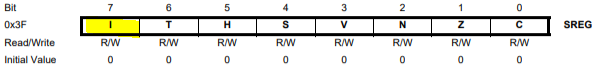
SREG register:
In this register we will use 7th bit ‘I’ which is Global interrupt enable bit. This bit must be enabled in order to use any interrupt in the ATtiny85 controller. Writing one to this enables this bit. Additionally every interrupt should be activated along with this Global interrupt enable bit.
TIMSK register:
Upon enabling the Global interrupt bit I in SREG we also need to enable compare match A associated interrupt. OCIE0A bit in TIMSK register is necessary to activate and deactivate compare match A interrupt. Hardware will clear the OCIE0A flag when interrupt routine is executed.
Steps to configure compare match with interrupt:
The below steps were written in the context to generate 1 sec time delay and toggle LED connected to PB1 using compare match with interrupts.
Configure the timer0 to operate in normal mode
Prescale the internal clock by a factor of 1024
According to the calculation store the compare value (161) in OCR0A
Enable Global interrupt enable I bit in SREG register
Enable OCIE0A bit in TIMSK register to enable Timer0 compare match interrupt.
Write the Interrupt service routine to repeat the operation 100 times to obtain a delay of 1 second.
Toggle the LED connected to the PB1 pin once the operation repeated 100 times.
Code:
#include<avr/io.h>
#define F_CPU 16500000UL
#include <avr/interrupt.h>
#include<util/delay.h>

int intr_count=0;

void comp_match()
{
 DDRB |= (1<<PB1); // set PB1 as output
 TCCR0A=0x00;
 TCCR0B=0x00;
 TCCR0B |= (1<<CS00)|(1<<CS02);   //prescaling with 1024
 TCCR0A|=(1<<WGM01);//toggle mode and compare match  mode
 OCR0A= 161; //compare value
 TCNT0=0;
 sei();   //enabling global interrupt
 TIMSK|=(1<<OCIE0A);
}

ISR (TIMER0_COMPA_vect)
{
  if (intr_count==100) //waiting for 100 count because to get 1 sec compare match should occur 100 times
  {
    PORTB^=(1<<PB1); //toggling the LED
    intr_count=0; //making intr_count=0 to continue the process
  }
  else  intr_count++; //incrementing intr_count
}

int main()
{
 comp_match();
 while(1)
 {

 }
 return 0;
}


 OCR0B is very similar to OCR0A register.
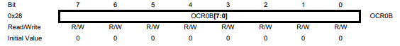
 In this register we will use 7th bit ‘I’ which is Global interrupt enable bit. This bit must be enabled in order to use any interrupt in the ATtiny85 controller. Writing one to this enables this bit. Additionally every interrupt should be activated along with this Global interrupt enable bit.
 Upon enabling the Global interrupt bit I in SREG we also need to enable compare match A associated interrupt. OCIE0A bit in TIMSK register is necessary to activate and deactivate compare match A interrupt. Hardware will clear the OCIE0A flag when interrupt routine is executed.


 Microcontroller")


